
Motor driving structure suitable for small gate

A technology of motor drive and gate, which is applied to the control mechanism of wing leaf, power control mechanism, special equipment for doors/windows, etc., and can solve the problem of motor drive structure damage, waste of cost and resources, etc. To achieve the effect of beautiful appearance, good trafficability and balanced structure

Pending Publication Date: 2018-11-06
佛山市圣田智能科技有限公司
View PDF0 Cites 2 Cited by
  • Summary
  • Abstract
  • Description
  • Claims
  • Application Information

AI Technical Summary

Problems solved by technology

[0004] Small electric gates are not too heavy due to the small span of the door leaf. Even now, many doors are made of aluminum alloy so the weight is relatively light. Therefore, using a large vertical motor to drive is a waste of cost and resources. The vertical shape of the vertical motor is large, which affects the overall aesthetics of the small electric gate. If it is installed on the top of the gate post, it will be abruptly raised by a large part. If it is installed at the bottom of the gate post, there will be various collisions and The possibility of electric leakage from blisters poses a great hidden danger to safety
[0005] Moreover, many installation places are doorway-type passage entrances and exits. If the vertical motor is installed vertically on the top of the gate post and is much higher than the gate leaf, then it is equivalent to making the gate leaf shorter in reverse, which will greatly affect the convenience of traffic
[0006] In addition, small electric gates are mainly installed in small and medium-sized entrances and exits where the flow of people is dense. The frequency of opening and closing is extremely high and the people who use them are diverse. If you don’t know that this is an electric gate, you will directly push the door leaf quickly and pass through it. For the coaxial and closely meshed motor drive structure of the vertical motor and the spur gear set, this artificial action of pushing the door will make the door open. The driven spur gear fixed to the shaft forcibly overspeeds the driving spur gear fixed to the output shaft of the motor, which is prone to tooth sweeping and damages and fails the motor drive structure of the small gate

Method used


Image

  • Motor driving structure suitable for small gate
  • Motor driving structure suitable for small gate
  • Motor driving structure suitable for small gate

Examples


Embodiment Construction

[0021] The idea, specific structure and technical effects of the present invention will be clearly and completely described below in conjunction with the embodiments and accompanying drawings, so as to fully understand the purpose, features and effects of the present invention. Apparently, the described embodiments are only some of the embodiments of the present invention, rather than all of them. Based on the embodiments of the present invention, other embodiments obtained by those skilled in the art without creative efforts belong to The protection scope of the present invention.

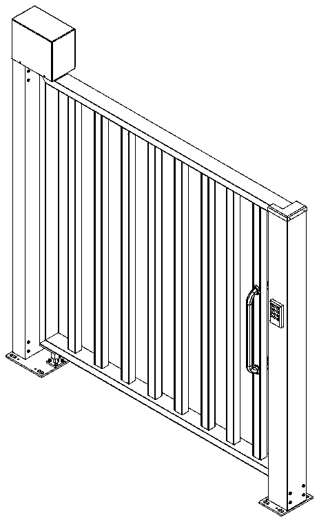
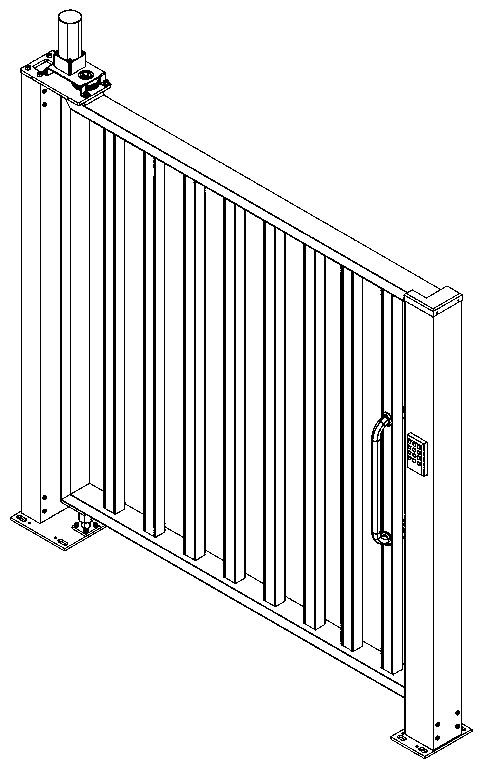
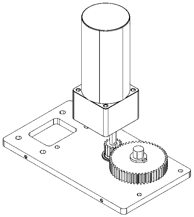
[0022] Such as Figure 4 to Figure 7 As shown, a motor drive structure suitable for a small gate, the proximal end of the door leaf 1 of the small gate is movably connected with the gate post 3 through the door shaft 2, and the motor drive structure is arranged on the top of the gate post 3, The motor drive structure includes a horizontal motor 4 that is horizontally arranged on the top of the do...


PUM


Abstract

The invention discloses a motor driving structure suitable for a small gate. According to the technical scheme, the near-shaft end of a door leaf of the small gate is movably connected with a doorpostthrough a door shaft, the motor driving structure is arranged at the top of the doorpost, the motor driving structure comprises a transversely-arranged motor which is located at the vertical plane the same as the vertical plane where the small gate is located and is horizontally arranged on the top of the doorpost, the output shaft of the transversely-arranged motor is perpendicular to the door shaft, a driving bevel gear fixedly connected with the output shaft of the transversely-arranged motor and a driven bevel gear fixedly connected with the door shaft are meshed with each other, and thedriving bevel gear and the driven bevel gear are in reducing gear combination. According to the structure, the opening and closing driving demand of the small gate can be met, the structure is small,moreover, the occupied vertical height is small, the maximization of the height of the door leaf is facilitated, moreover, the structure is integrated with the small gate, so that the overall appearance is attractive, meanwhile, the fault-tolerant function is achieved, damage can not be caused when the door is forcibly pushed by external force, and the durability of the product is ensured.

Description

technical field [0001] The invention relates to the technical field of electric gates, in particular to a motor driving structure suitable for small gates. Background technique [0002] see Figure 1 ~ Figure 3 As shown, due to the large span and heavy weight of each door leaf, the traditional large electric gate with door leaf opening and closing uses a large vertical motor in its motor drive structure, and the output shaft of the vertical motor is set in the same direction as the door shaft. The driving spur gear fixed to the motor output shaft and the driven spur gear fixed to the door shaft are coaxial and tightly meshed, so that the torque output by the motor can be transmitted to the rotation process of the door shaft without loss. [0003] With the improvement of people's living standards, due to the convenience of electric gates, there is a widespread demand for installing small electric gates in many small and medium-sized exits or passages. [0004] Small electric...

Claims


Application Information

Patent Timeline
IPC IPC(8): E05F15/614E06B11/00E06B7/28
CPCE05F15/614E06B7/28E06B11/00
Inventor 周仲辉
Owner 佛山市圣田智能科技有限公司
Learn More