Exhaust gas recirculation (EGR) valve assembly

A technology of exhaust gas recirculation valve and assembly, which is used in exhaust gas recirculation, engine components, machines/engines, etc., can solve the problem of insufficient exhaust gas treatment, substandard exhaust gas emission, and poor valve opening and valve opening accuracy. control issues

Inactive Publication Date: 2018-11-06
温州汇众汽车电器有限公司
View PDF0 Cites 0 Cited by
  • Summary
  • Abstract
  • Description
  • Claims
  • Application Information

AI Technical Summary

Problems solved by technology

The movement of the valve stem is generally driven by a motor connected through a worm gear structure or by driving the eccentric wheel to rotate and press the valve stem, and some are directly connected by a stepping motor. In these structures, the opening accuracy of the valve port and the valve plate is still not very good. The control of exhaust gas makes the exhaust gas treatment insufficient, and eventually the exhaust

Method used


Image

  • Exhaust gas recirculation (EGR) valve assembly
  • Exhaust gas recirculation (EGR) valve assembly
  • Exhaust gas recirculation (EGR) valve assembly

Examples


Embodiment Construction

[0017] The following specific descriptions of the present invention are given by the examples, which are only used to further illustrate the present invention, and should not be construed as limiting the protection scope of the present invention.

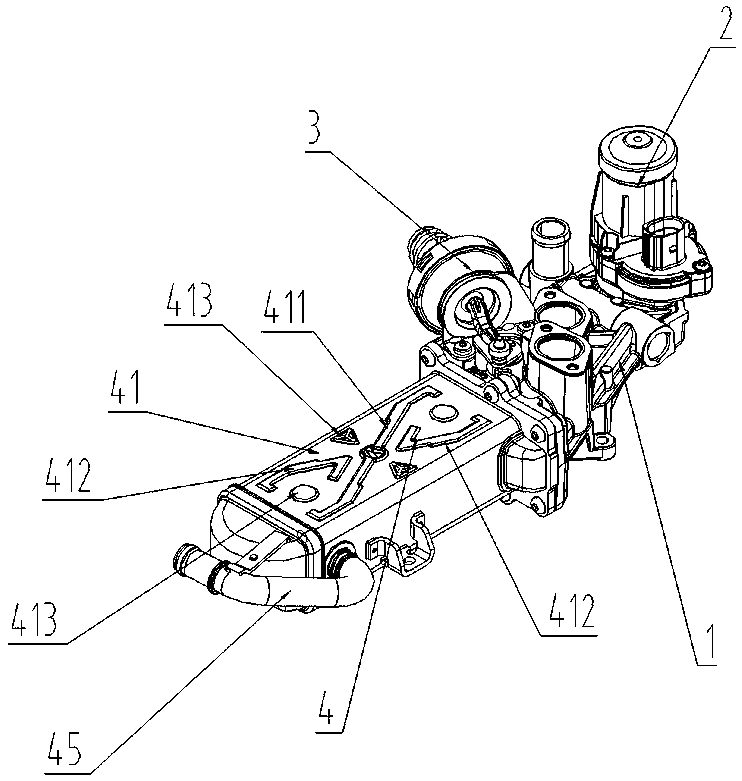
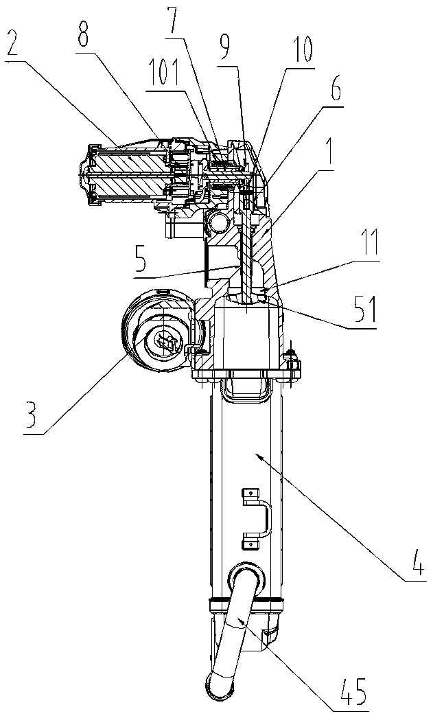
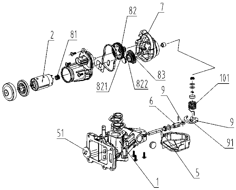
[0018] like figure 1 — Figure 4 As shown, the present invention discloses an EGR exhaust gas recirculation valve assembly, including a valve body 1, a motor 2, a vacuum valve 3 and a cooler 4, the motor 2 and the vacuum valve 3 are installed on the valve body 1, and the valve body 1 The opening is connected with the cooler 4. The valve body 1 is provided with a valve port 11 for exhaust gas to pass through. The valve stem 5 is installed in the valve body 1. The front end of the valve stem 5 is provided with a valve plate 51 that blocks the valve port 11. Inside the valve body 1 The position corresponding to the tail end of the valve stem 5 is provided with an output shaft 7, and the rotating shaft of the motor 2 is connected with ...


PUM


Abstract

The invention discloses an exhaust gas recirculation (EGR) valve assembly which comprises a valve body, a motor, a vacuum valve and a cooler. The motor and the vacuum valve are mounted on the valve body, and an opening of the valve body is connected with the cooler. A rotary shaft of the motor is connected with an output shaft through a reduction gear set. The end of the output shaft is connectedwith a driving septum board in a sleeved mode, and a U-shaped shifting fork is arranged at the tail end of a valve rod. A bearing is mounted in an opening groove of the shifting fork, and an arc-shaped hook groove is formed in the driving septum board. The bearing is arranged in the hook groove, and the output shaft is connected with a returning torsional spring in a sleeved mode. Supporting feetof the returning torsional spring are inserted into the driving septum board. The cooler is provided with a shell, and first reinforcing ribs which are arranged in the diagonal direction of the side wall are further convexly arranged on the side wall of the shell. Hook-shaped second reinforcing ribs are convexly arranged in the staggered symmetrical direction of the first reinforcing ribs correspondingly, and reinforcing blocks are further convexly arranged in spaces between the first reinforcing ribs and the second reinforcing ribs. Thus, the technical effects that exhaust gas circulation isaccurate, the cooling effect is good, and the structure is reliable are achieved.

Description

technical field [0001] The invention relates to a control valve assembly in an exhaust gas circulation system in an engine, in particular to an EGR exhaust gas recirculation valve assembly. Background technique [0002] The EGR exhaust gas recirculation valve assembly is used in the exhaust emission system of the automobile engine. It is the most ideal product to solve the exhaust emission at present. It can reduce the nitrogen oxides and hydrocarbons generated by the high temperature of the engine during the driving process of the automobile, so that the exhaust emission can reach the standard. . [0003] The traditional EGR exhaust gas recirculation valve assembly has a valve body and a cooler. The valve body has a valve port and a valve stem, and the valve stem is provided with a valve plate for blocking the valve port. The movement of the valve stem is generally driven by a motor connected through a worm gear structure or by driving the eccentric wheel to rotate and pre...

Claims


Application Information

Patent Timeline
IPC IPC(8): F02M26/65F02M26/73F02M26/54
CPCF02M26/65F02M26/54F02M26/73
Inventor 戴斌裕
Owner 温州汇众汽车电器有限公司
Why Eureka
Try Eureka