
Dehumidifier, cooling mechanism of dehumidifier and cooling method

A dehumidifier and compressor technology, applied in heating methods, household heating, space heating and ventilation details, etc., can solve problems such as affecting the life of the compressor, deformation and damage of injection molding parts, etc., and achieve the effect of saving energy

Pending Publication Date: 2018-11-06
GREE ELECTRIC APPLIANCES INC
View PDF0 Cites 0 Cited by
  • Summary
  • Abstract
  • Description
  • Claims
  • Application Information

AI Technical Summary

Problems solved by technology

[0002] The dehumidifier uses the compressor to dehumidify. During the long-term dehumidification process, the temperature of the compressor cylinder and exhaust pipe is higher than 70°. Especially during a period of shutdown, the temperature of the compressor chamber is higher due to no air flow. , it may cause deformation and damage to the injection molded parts around the compressor, which will seriously affect the life of the compressor

Method used


Image

  • Dehumidifier, cooling mechanism of dehumidifier and cooling method
  • Dehumidifier, cooling mechanism of dehumidifier and cooling method
  • Dehumidifier, cooling mechanism of dehumidifier and cooling method

Examples


Embodiment 1

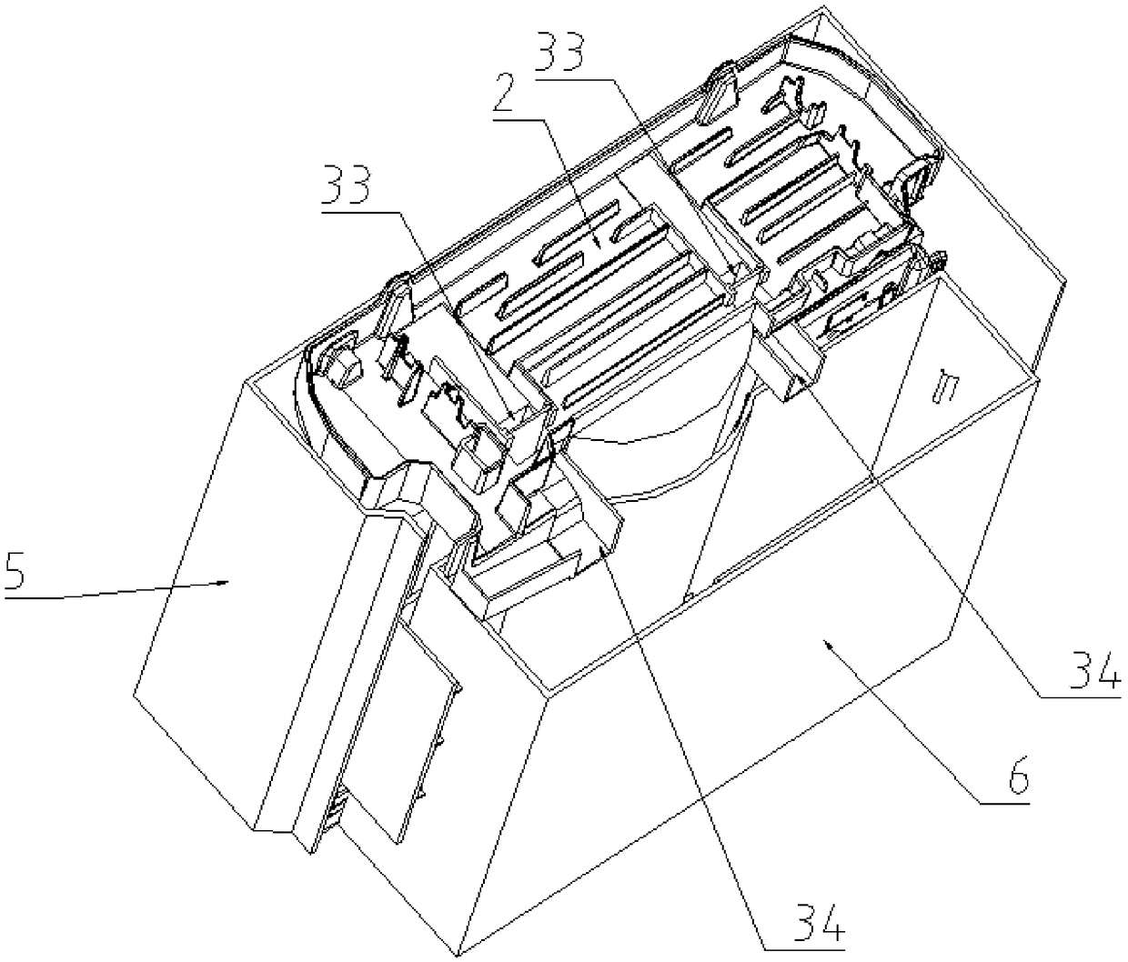
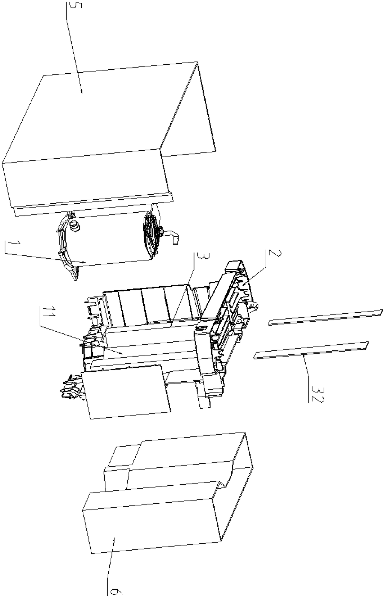
[0027] Such as Figure 1-4 Shown is a cooling mechanism for a dehumidifier, the dehumidifier includes a compressor 1 and a water receiving tray 2 for storing water generated during the dehumidification process, a compressor chamber 11 is formed under the water receiving tray 2, The compressor 1 is at least partially located in the compressor cavity 11 , and the cooling mechanism 3 is arranged in the compressor cavity 11 .

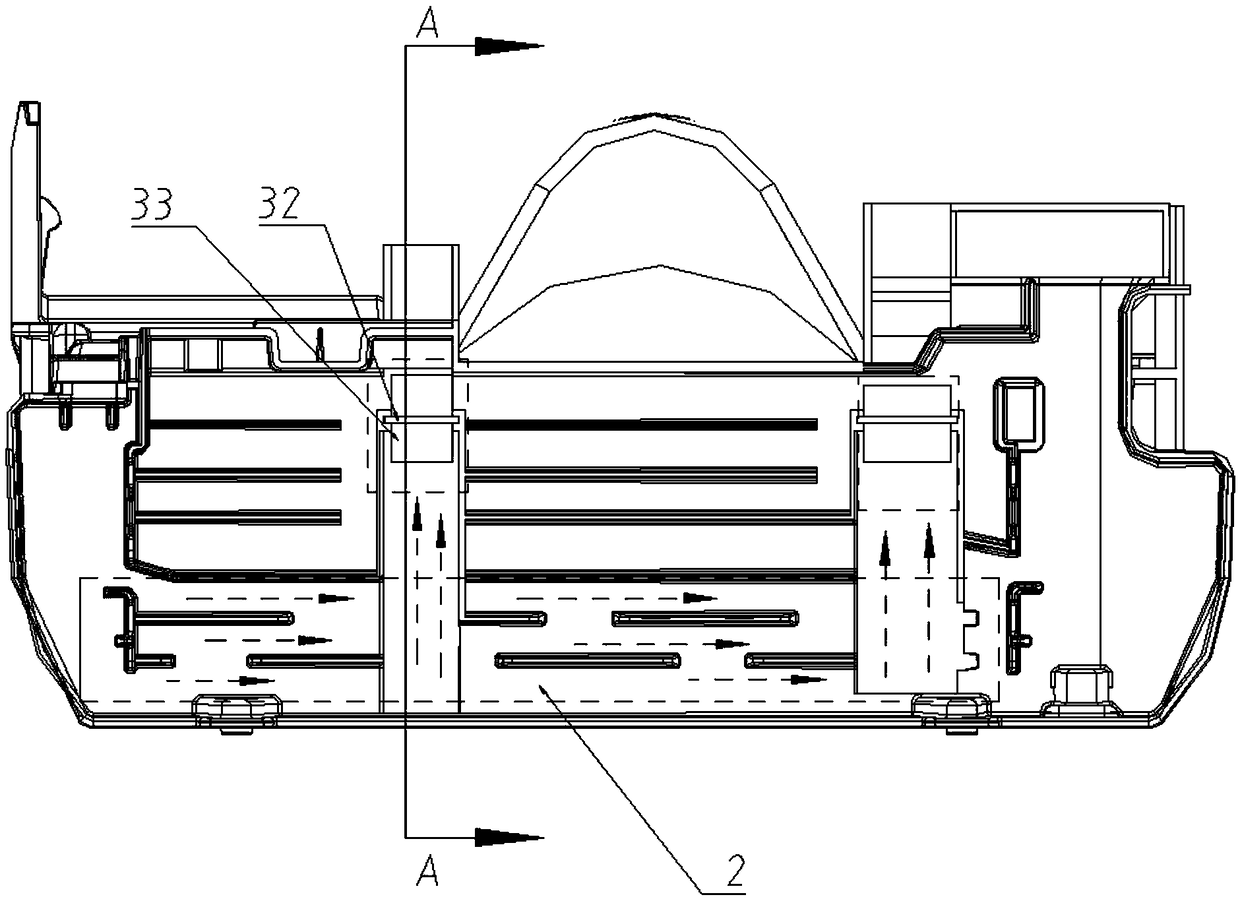
[0028] The cooling mechanism 3 includes a water channel 31 arranged below the water receiving tray 2 and a splint 32 inserted into the water channel 31, the upper ends of the splint 32 and the water channel 31 are fixed to the water receiving tray 2, and the splint 32 divides the water channel 31 into The cold runner and the hot runner communicate at the bottom of the water channel 31 .

[0029] A water inlet 33 is arranged on the cold runner, and the water inlet 33 is arranged in the water receiving tray 2 so that the condensed water in the water receivin...

Embodiment 2

[0037] For dehumidifiers with low dehumidification power, when the amount of condensed water is too small, the cooling effect of the cooling mechanism in the first embodiment is difficult to achieve. In view of this situation, one or more copper can be vertically arranged in the water channel 31 of the first embodiment. The lower end of the copper sheet extends to the bottom near the water channel 31, and the upper end is in contact with the evaporator or heat exchanger of the dehumidifier, and the heat in the water channel 31 can be transferred to the evaporator or heat exchanger through the copper sheet. Since the aluminum sheet for heat dissipation is arranged on the evaporator or the heat exchanger, the heat on the aluminum sheet can be transferred out through air cooling, and thus the heat generated by the compressor can be transferred out. The evaporator or heat exchanger belongs to the prior art and will not be described in detail here.


PUM


Abstract

The invention relates to a cooling mechanism of a dehumidifier. The dehumidifier comprises a compressor cavity for containing a compressor. The cooling mechanism comprises a water channel formed in the compressor cavity, and a clamping plate dividing the water channel into a cold runner and a hot runner; the cold runner communicates with the hot runner at the bottom of the water channel; and the water channel is provided with a water inlet on one side of the cold runner and a water outlet on one side of the hot runner. The cooling mechanism is automatically started according to the temperature, is free from influence of the operation of the dehumidifier, and can achieve a better dehumidification effect in the dehumidification process and after the dehumidifier is shut down.

Description

technical field [0001] The invention relates to the field of dehumidifiers, in particular to a dehumidifier cooling mechanism, a dehumidifier with the cooling mechanism and a cooling method. Background technique [0002] The dehumidifier uses the compressor to dehumidify. During the long-term dehumidification process, the temperature of the compressor cylinder and exhaust pipe is higher than 70°. Especially during a period of shutdown, the temperature of the compressor chamber is higher due to no air flow. , it may cause deformation and damage to the injection molded parts around the compressor, which will seriously affect the life of the compressor. Contents of the invention [0003] In view of this, the present invention provides a cooling mechanism for a dehumidifier, which can automatically cool down according to the temperature around the compressor, and then reduce the temperature of the compressor to avoid excessive temperature damage to the compressor and surroundi...

Claims


Application Information

Patent Timeline
IPC IPC(8): F24F3/14F24F13/22F24F13/30
CPCF24F3/1405F24F13/22F24F13/30
Inventor 李宗权李小怀黄家璟候帅飞胡树锋马江辉陈寒冬
Owner GREE ELECTRIC APPLIANCES INC
Learn More