Eureka AIR delivers breakthrough ideas for toughest innovation challenges, trusted by R&D personnel around the world.

Relay failure detection method, device and system for photovoltaic grid-connected inverter

A detection method and detection device technology, which are applied in measurement devices, circuit breaker tests, instruments, etc., can solve problems such as increased hardware costs, waste of digital processing chip resources, and easy misjudgment of relay failures.

Active Publication Date: 2020-08-28
SUNGROW POWER SUPPLY CO LTD
View PDF5 Cites 6 Cited by
  • Summary
  • Abstract
  • Description
  • Claims
  • Application Information

AI Technical Summary

Problems solved by technology

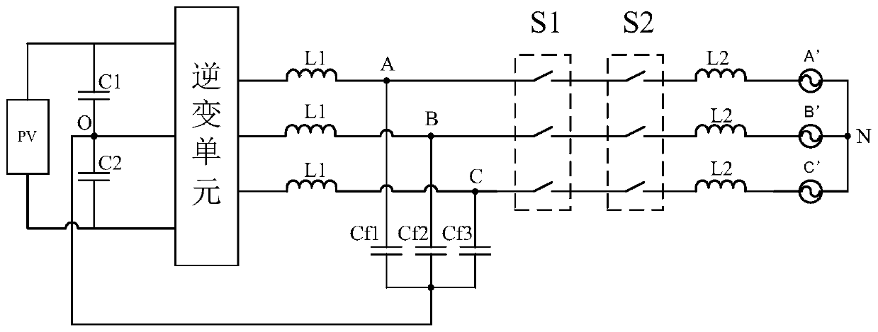
Similarly, when judging the relay failure of phase B and phase C, it is necessary to collect the inverter voltage Vinv_B and Vinv_C of phase B and phase C respectively, and the grid voltage Vac_B and Vac_C of phase B and phase C, which requires three inverters The inverter voltage sampling circuit and the three power grid voltage sampling circuits, the digital processing chip (such as DSP) in the inverter also needs a corresponding number of sampling ports, resulting in an increase in hardware costs and a waste of digital processing chip resources. The voltage Vinv is generally sampled relative to the neutral point of the power grid. When the relay is disconnected, Vinv collects the floating voltage, which leads to the poor definition of the relay fault judgment thresholds ΔV1 and ΔV2, and it is easy to misjudge the relay fault.

Method used


Image

  • Relay failure detection method, device and system for photovoltaic grid-connected inverter
  • Relay failure detection method, device and system for photovoltaic grid-connected inverter
  • Relay failure detection method, device and system for photovoltaic grid-connected inverter

Examples


Embodiment Construction

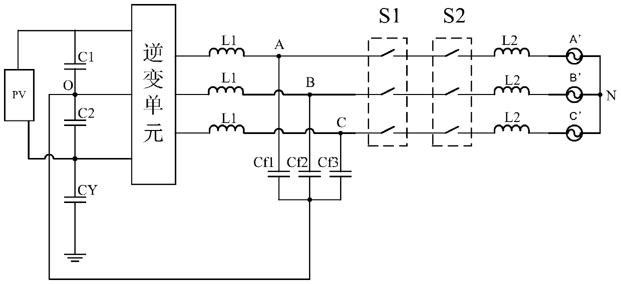
[0055] see figure 2 , figure 2 A schematic structural diagram of a photovoltaic grid-connected inverter system applied to a relay failure detection method of a photovoltaic grid-connected inverter provided by an embodiment of the present invention, wherein the photovoltaic grid-connected inverter system includes bus capacitors (C1 and C2), the first capacitor CY, the inverter unit 201, the first relay S1, the second relay S2 and the filter module.

[0056] Wherein, the filter module may be an LCL filter, including an inductor L1, an inductor L2, and a capacitor Cf. The bus capacitor has a target midpoint O, and the photovoltaic grid-connected inverter system has a grid neutral point N.

[0057] The first capacitor CY can be set between the output negative electrode PV- of the photovoltaic grid-connected inverter and the ground, and can also be set at other suitable positions, such as between PV+ and the ground, and the suitable position can be based on actual conditions. ...


PUM


Abstract

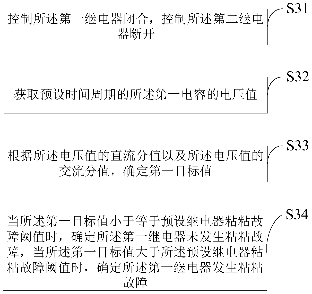
The embodiments of the present invention provide a relay failure detection method, device and system for a photovoltaic grid-connected inverter. According to the method, a first relay is controlled tobe switched on, and a second relay is controlled to be switched off; the voltage value of a first capacitor during a preset time period is obtained, and a first target value is determined according to the direct current branch value of the voltage value and the alternating current branch value of the voltage value; and when the first target value is smaller than or equal to a preset relay adhesion fault threshold, it is determined that the first relay does not undergo an adhesion fault, and when the first target value is greater than the preset relay adhesion fault threshold, it is determinedthat the first relay undergoes an adhesion fault. According to the technical schemes of the invention, the voltage value of the first capacitor is detected and is compared with the preset threshold,so that whether the relay undergoes a fault can be determined, that is, only one voltage is required to be collected, and therefore, the cost of detection hardware and the resources of a digital processing chip can be saved; since the feature of the preset threshold is obvious, a judgment result is reliable, and therefore, the accuracy of detection can be improved.

Description

technical field [0001] The invention relates to the technical field of new energy power generation, in particular to a relay failure detection method, device and system of a photovoltaic grid-connected inverter. Background technique [0002] The photovoltaic grid-connected inverter is a power conversion device connected between the PV photovoltaic panel and the grid, and its function is to convert the direct current generated by the photovoltaic photovoltaic panel into alternating current. For safety reasons, the inverter is required to disconnect the inverter from the grid in time when it detects some abnormal conditions. [0003] At present, the mainstream photovoltaic grid-connected inverters (such as string type and distributed photovoltaic grid-connected inverters) need to be isolated by relays on the inverter side and the grid side. When the inverter detects an abnormal situation, it will break open, cut off the inverter from the grid in time. [0004] Specifically, ...

Claims


Application Information

Patent Timeline
Patent Type & Authority Patents(China)
IPC IPC(8): G01R31/327
CPCG01R31/3278
Inventor 文鹏陈鹏曹金虎耿后来
Owner SUNGROW POWER SUPPLY CO LTD
Why Eureka
Eureka Blog
Learn More