Eureka AIR delivers breakthrough ideas for toughest innovation challenges, trusted by R&D personnel around the world.

Blast furnace molten iron silicon content change trend prediction method, device and storage medium

A blast furnace hot metal, change trend technology, applied in the direction of forecasting, complex mathematical operations, data processing applications, etc., can solve the problems that the accuracy of the model cannot be guaranteed, the division method is rough, and the comprehensive information cannot be reflected.

Active Publication Date: 2018-11-06
CENT SOUTH UNIV
View PDF9 Cites 29 Cited by
  • Summary
  • Abstract
  • Description
  • Claims
  • Application Information

AI Technical Summary

Problems solved by technology

[0005] The present invention provides a method, equipment and storage medium for predicting the change trend of silicon content in blast furnace molten iron, which overcomes the above problems or at least partially solves the above problems, and solves the problem of silicon content trend prediction methods in the prior art. The difference between the two heats before and after is used to define the trend. The division method is relatively rough and cannot reflect comprehensive information, and the accuracy of the model used for forecasting cannot be guaranteed.

Method used


Image

  • Blast furnace molten iron silicon content change trend prediction method, device and storage medium
  • Blast furnace molten iron silicon content change trend prediction method, device and storage medium
  • Blast furnace molten iron silicon content change trend prediction method, device and storage medium

Examples


Embodiment Construction

[0026] The specific implementation manners of the present invention will be further described in detail below in conjunction with the accompanying drawings and embodiments. The following examples are used to illustrate the present invention, but are not intended to limit the scope of the present invention.

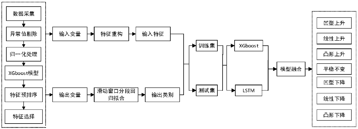
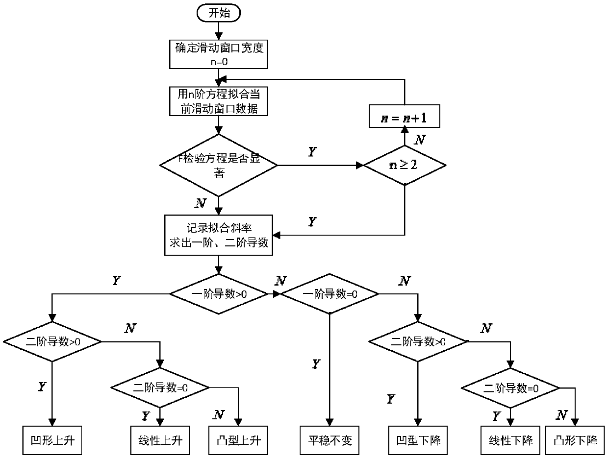
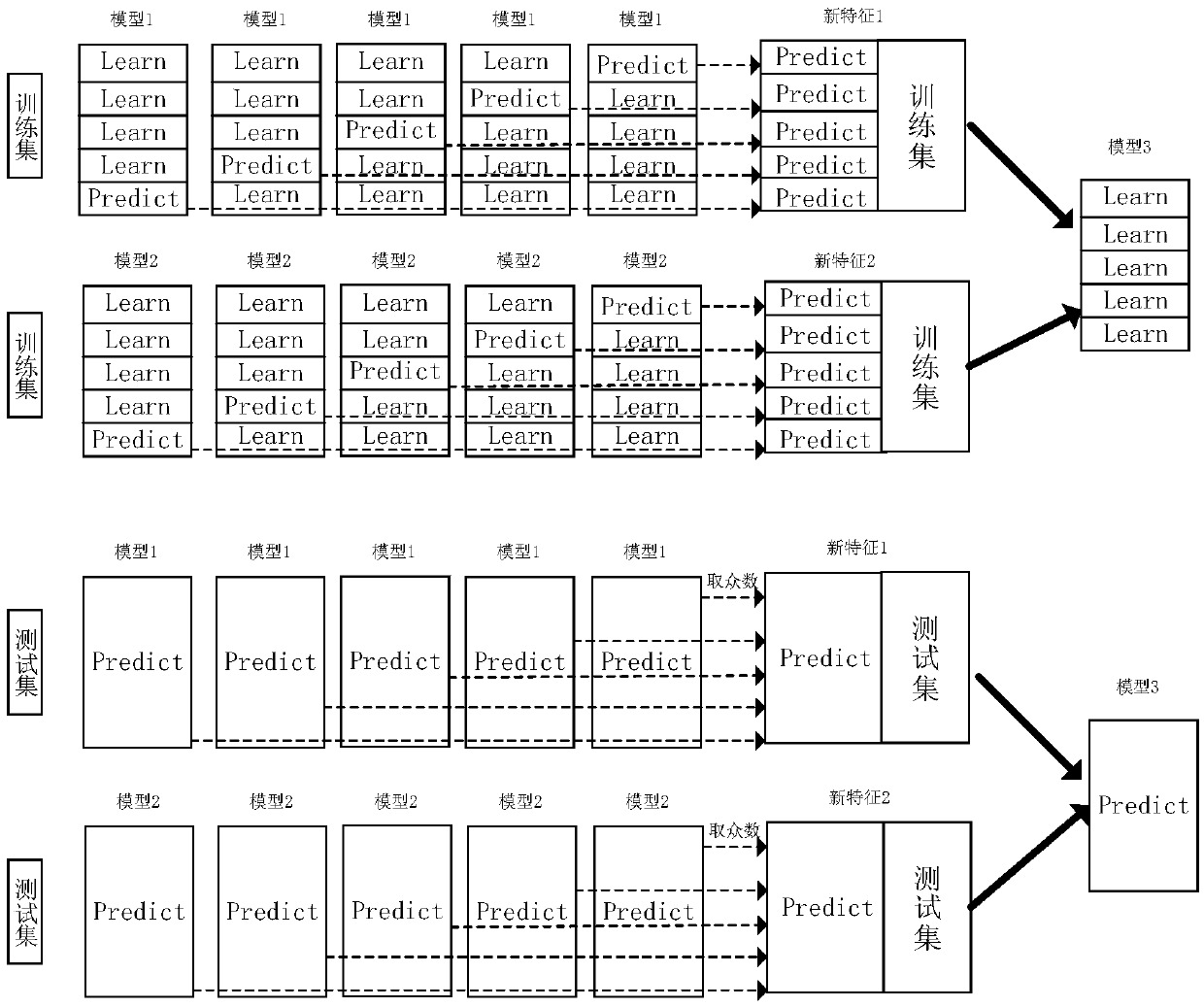
[0027] This embodiment shows a method for predicting the change trend of silicon content in blast furnace molten iron, such as figure 1 shown, including:

[0028] Obtain the characteristic parameters related to the change of silicon content in blast furnace hot metal during the ironmaking process, and predict the change trend of silicon content based on the trained silicon content prediction model of blast furnace hot metal;

[0029] Wherein, the blast furnace molten iron content prediction model includes a first-level prediction model and a second-level prediction model, the first-level prediction model is used to make preliminary predictions on the silicon content chang...


PUM


Abstract

The invention provides a blast furnace molten iron silicon content change trend prediction method, a blast furnace molten iron silicon content change trend prediction device and a storage medium. Themethod includes the step that characteristic parameters during an iron making process which are related to silicon content change in blast furnace molten iron are acquired, and a silicon content change trend is predicted on the basis of trained blast furnace molten iron silicon content prediction models, wherein the blast furnace molten iron silicon content prediction models include a first layerprediction model and a second layer prediction model, wherein the first layer prediction model is used for preliminarily predicting the silicon content change trend according to an original sample, and the second layer prediction model predicts the silicon content change trend for the second time according to the prediction result of the first layer prediction model so as to obtain the silicon content change trend. According to the blast furnace molten iron silicon content change trend prediction method, the blast furnace molten iron silicon content change trend prediction device and the storage medium of the invention, a limit gradient enhancement and long-term and short-term memory network fusion model is established to predict the trend of the silicon content in the molten iron, a reference basis is provided for a blast furnace operator to judge the change trend of the condition of the blast furnace and control the amplitude of the blast furnace in advance, and therefore, the smoothness of the iron making process can be ensured, and the quality of the molten iron can be maintained within a normal range.

Description

technical field [0001] The present invention relates to the technical field of automatic control of blast furnace smelting, and more particularly, relates to a method, equipment and storage medium for predicting the change trend of silicon content in blast furnace molten iron. Background technique [0002] Blast furnace smelting is a continuous production process, the operation of the furnace is complex, and there are many physical and chemical reactions. Blast furnace temperature, that is, the temperature of molten iron in the hearth, is one of the important parameters to measure the condition of the blast furnace. If it is too high or too low, it will cause the quality of molten iron to decline and the furnace condition to be unsatisfactory. The furnace temperature is low, the physical heat of molten iron is insufficient, and the heat reserve of the hearth is insufficient, which may easily cause hearth freezing accidents; the furnace temperature is high, and the gas flow i...

Claims


Application Information

Patent Timeline
IPC IPC(8): G06Q10/04G06F17/18
CPCG06F17/18G06Q10/04
Inventor 蒋朝辉蒋珂谢永芳桂卫华阳春华潘冬陈致蓬
Owner CENT SOUTH UNIV
Why Eureka
Eureka Blog
Learn More