Forced cooling type radial flux permanent magnet synchronous motor based on plate winding

A permanent magnet synchronous motor, radial magnetic flux technology, applied in the shape/style/structure of winding conductors, synchronous machine parts, windings, etc., can solve the problem of low winding full slot ratio, short service life, poor heat dissipation effect, etc. problems, to achieve the effect of low overall cost, reduced volume and weight, and good air cooling

Active Publication Date: 2018-11-06
李洋涛
View PDF4 Cites 0 Cited by
  • Summary
  • Abstract
  • Description
  • Claims
  • Application Information

AI Technical Summary

Problems solved by technology

[0004] In view of the above-mentioned deficiencies in the prior art, the purpose of the present invention is to solve the problems of the existing radial permanent magnet motors, such as low full slot rate of windings, small power-to-weight ratio, poor heat dissipation, low reliability and short service life, and provide a A strong-cooled radial flux permanent magnet synchronous motor based on plate windings, which can make the windings have a higher full slot rate, a larger power-to-weight ratio, a shorter magnetic circuit, low reluctance, and higher efficiency; and inside the motor Set up a forced cooling structure, so as to effectively improve the heat dissipation effect of the entire motor, improve the reliability of the motor, and prolong the service life of the motor

Method used


Image

  • Forced cooling type radial flux permanent magnet synchronous motor based on plate winding
  • Forced cooling type radial flux permanent magnet synchronous motor based on plate winding
  • Forced cooling type radial flux permanent magnet synchronous motor based on plate winding

Examples


Embodiment

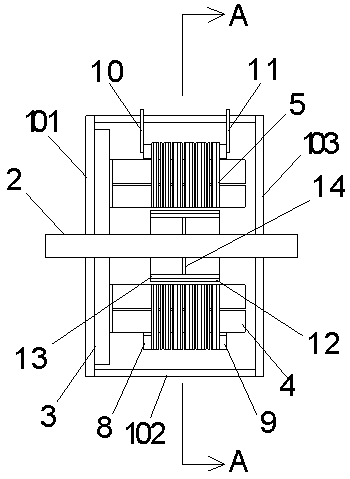
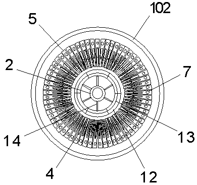
[0026] Example: see Figure 1 to Figure 4 , a forced cooling radial flux permanent magnet synchronous motor based on plate windings, including a motor housing, a motor shaft 2 and several windings. The motor housing includes a left end cover 101, a cylindrical housing 102 and a right end cover 103 connected together, one end of the motor shaft 2 passes through the left end cover 101 and the right end cover 103 in sequence, and the shaft of the motor shaft 2 The center line coincides with the axis center line of the cylindrical housing 102, and is rotatably connected with the left end cover 101 and the right end cover 103 through bearings. A connection plate 3 is arranged inside the left end cover 101 or the right end cover 103, and one side of the connection plate 3 is fixedly connected with the left end cover 101 or the right end cover 103 by bolts; The longitudinal direction of the slot coincides with the radial direction of the cylindrical housing 102 .

[0027] The windi...


PUM


Abstract

The invention discloses a forced cooling type radial flux permanent magnet synchronous motor based on a plate winding. The forced cooling type radial flux permanent magnet synchronous motor comprisesa motor shell, a motor shaft and a plurality of windings, wherein each winding comprises a plurality of winding units, and each winding unit is formed by connecting a plurality of winding copper sheets; each winding copper sheet comprises an inserted connection sheet and two legs, a plurality of silicon steel sheets are arranged on each leg, a through hole is formed in the outer end of each silicon steel sheet, and the silicon steel sheets of each winding copper sheet cling together respectively, so that through holes in the silicon steel sheets form a via through passage; a water inlet channel is formed in one side of each silicon steel sheet, and a water outlet channel is formed in the other side of each silicon steel sheet; and on the motor shaft, a plurality of permanent magnets are distributed on the periphery of the motor shaft, and the magnetic poles of every two adjacent permanent magnets are opposite. According to the forced cooling type radial flux permanent magnet synchronous motor, the thankful rate of the winding can be higher, the ratio of power to weight is larger, the magnetic circuit is shorter, the magnetic resistance is low, and the efficiency is higher; and a forced cooling mechanism is arranged inside the motor, so that the cooling effect of the whole motor is improved effectively, the reliability of the motor is improved, and the service life of the motoris prolonged.

Description

technical field [0001] The invention relates to the technical field of motors, in particular to a forced cooling radial flux permanent magnet synchronous motor based on plate windings. Background technique [0002] The current permanent magnet motors mainly include radial flux permanent magnet motors and axial flux permanent magnet motors. Among them, the existing radial flux permanent magnet motors mainly attach the magnetic sheet to the cylindrical motor shell On the inner wall of the body, and then install the silicon steel sheet in the motor housing, and then wind the copper wire on the silicon steel sheet, this assembly method is usually called "off-line". However, such a structure has a long magnetic path, resulting in large reluctance and high iron loss, and because the winding copper wire is a circular cross section, there is an inevitable gap between the copper wires, which not only leads to a low full slot rate of the copper wire, but also a small conductive area a...

Claims


Application Information

Patent Timeline
Patent Type & Authority Applications(China)
IPC IPC(8): H02K21/02H02K3/04H02K1/20
CPCH02K1/20H02K3/04H02K21/02H02K2203/06
Inventor 李洋涛王昌茂
Owner 李洋涛
Why Eureka
Try Eureka