Sealing device for changing the full groove ratio of the sealing ring
A sealing device and sealing ring technology, which is applied to fluid pressure actuating devices, piston rings, actuator accumulators, etc., can solve the problems of high leakage rate and poor dynamic performance, reduce the full slot rate and improve dynamic The effect of high performance and full slot rate
- Summary
- Abstract
- Description
- Claims
- Application Information
AI Technical Summary
Problems solved by technology
Method used
Image
Examples
Embodiment 1
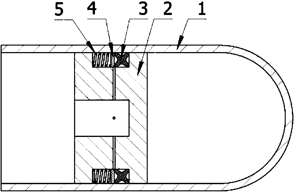
[0022] Such as figure 1 As shown, this embodiment is a sealing device for changing the full groove rate of the sealing ring, which includes a cylinder 1 with an opening at one end and a sealing piston 2 arranged in the cylinder 1;
[0023] The contact surface between the sealing piston 2 and the cylinder body 1 is provided with a sealing groove; in the sealing groove, an X-shaped sealing ring 3, a retaining ring 4 and several springs 5 are sequentially arranged in the axial direction from the sealing end of the cylinder body to the opening end; The original length of the spring 5 is greater than the distance between the side wall of the sealing groove and the retaining ring 4;
[0024] The center of the end face of the sealing piston 2 corresponding to the opening of the cylinder 1 is provided with a blind hole; the blind hole communicates with the sealing groove through a through hole; the outlet of the through hole is arranged at the retaining ring 4 and the between the a...
Embodiment 2
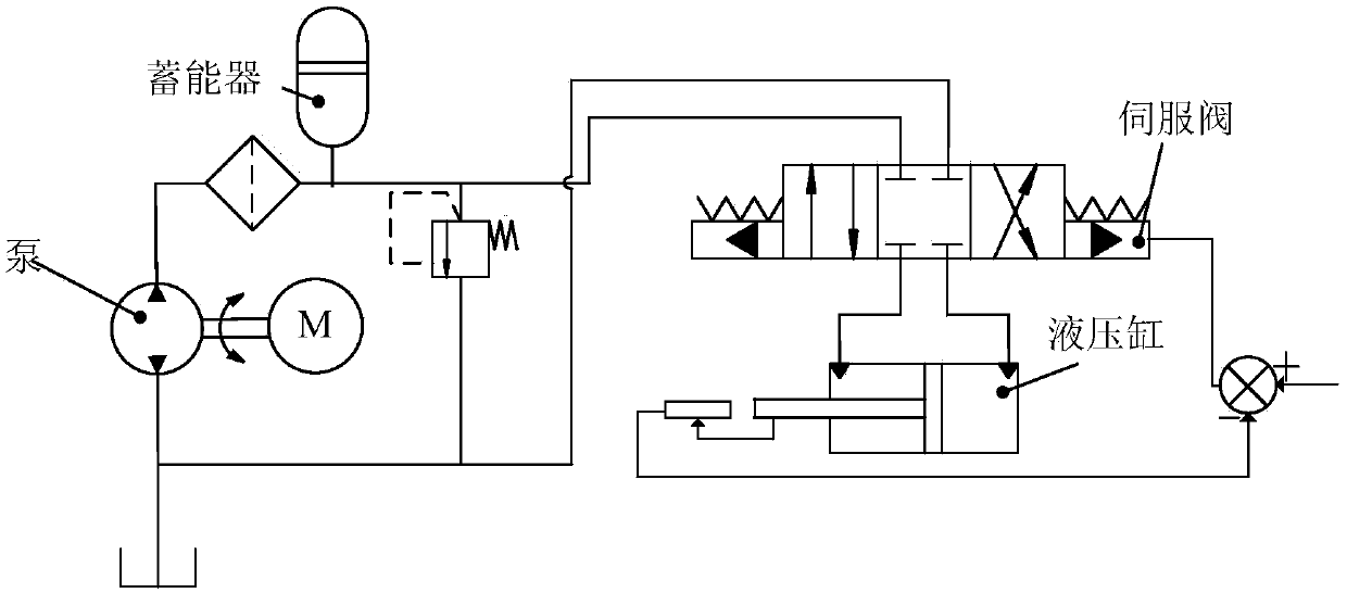
[0029] Such as figure 2 As shown, the sealing device in this embodiment takes the accumulator in the hydraulic system as an example, including a cylinder 1 with one end in communication with the pump outlet of the hydraulic system and the inlet passage of the servo valve, and a sealing piston 2 arranged in the middle of the cylinder;
[0030] One side of the sealing piston 2 is provided with oil connected to the hydraulic system, and the other side is provided with high-pressure gas; the contact surface between the sealing piston 2 and the cylinder body 1 is provided with a sealing groove; From the sealing end to the open end, an X-shaped sealing ring 3, a retaining ring 4 and a plurality of springs 5 are arranged in sequence; The X-shaped sealing ring 3 contacts, and the original length of the spring 5 is greater than the distance between the side wall of the sealing groove and the retaining ring 4;
[0031] The sealing piston 2 is provided with a blind hole in the center...
Embodiment 3
[0036] Based on the above embodiments, the X-shaped sealing ring 3 in this embodiment is a fluorine rubber sealing ring, and the X-shaped sealing ring 3 is an X-shaped rubber bowl and / or a rotating lip-shaped sealing ring;
[0037] The fluorine rubber of this embodiment has outstanding heat resistance and oil resistance, and the rubber bowl and the rotating lip seal ring can significantly improve the service time.
PUM
 Abstract
Description
Claims
Application Information
 - R&D
- Intellectual Property
- Life Sciences
- Materials
- Tech Scout
- Unparalleled Data Quality
- Higher Quality Content
- 60% Fewer Hallucinations
Browse by: Latest US Patents, China's latest patents, Technical Efficacy Thesaurus, Application Domain, Technology Topic, Popular Technical Reports.
© 2025 PatSnap. All rights reserved.Legal|Privacy policy|Modern Slavery Act Transparency Statement|Sitemap|About US| Contact US: help@patsnap.com


