A 6-way interleaved parallel boost PFC circuit

A circuit and parallel technology, applied in electrical components, regulating electrical variables, high-efficiency power electronic conversion, etc., can solve the problems of small output power, large current and voltage withstand of switching devices, large current ripple, etc.

Active Publication Date: 2019-09-17
HANGZHOU DIANZI UNIV
View PDF3 Cites 0 Cited by
  • Summary
  • Abstract
  • Description
  • Claims
  • Application Information

AI Technical Summary

Problems solved by technology

[0005] Aiming at the deficiencies of the prior art, the present invention provides a 6-way interleaved parallel Boost PFC circuit, which is used to overcome the traditional power factor correction circuit Boost inductance, small output power, large current and voltage of the switching device of the circuit, and current ripple. Disadvantages such as Boda

Method used


Image

  • A 6-way interleaved parallel boost PFC circuit
  • A 6-way interleaved parallel boost PFC circuit
  • A 6-way interleaved parallel boost PFC circuit

Examples


Embodiment Construction

[0029] The technical solutions provided by the present invention will be further described below in conjunction with the accompanying drawings.

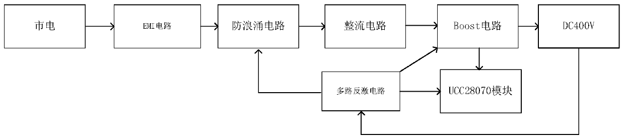
[0030] In the prior art, improving the power of PFC generally proceeds from the following aspects, one is the application of new power devices; Nowadays, two-stage interleaved parallel power factor correction can handle most applications, and its power can reach 5KW or even higher. For example, the UCC28070 chip produced by TI provides a two-stage interleaved circuit design. However, how to use the existing two-level interleave chip to realize multi-level interleave has become an urgent problem to be solved in the prior art.

[0031] The technical idea of ​​the present invention is to use a synchronous clock signal to combine multiple PFC chips. For example, three UCC28070 chips are separated by providing synchronous signals for chip working periods. Because a single UCC28070 chip provides a two-stage interleaved circuit design, Th...


PUM


Abstract

The invention discloses a 6-way interleaved parallel Boost PFC circuit, which comprises a Boost circuit, a multi-way flyback circuit, an anti-surge circuit, a UCC28070 module, a rectifier circuit and an EMI circuit. The input end of the EMI circuit is connected to the mains, the output end is connected to the input end of the anti-surge circuit, the input end of the rectification circuit is connected to the output end of the anti-surge circuit, the output end is connected to the Boost circuit, the control end of the Boost circuit is connected to UCC28070, and the output of the Boost circuit 400V DC voltage, multi-channel flyback circuit input terminals connected to Boost output DC400V output terminals respectively provide power to the anti-surge circuit, Boost circuit, and UCC28070 module. The current ripple of the Boost PFC circuit of the present invention is small, and the stress of the switching device and the size of the boosting inductance are reduced.

Description

technical field [0001] The invention belongs to the technical field of charging power supply, and relates to a power factor correction of a large-scale and high-power battery charging system, in particular to a power factor correction that can adopt the AC power of 220V / 50Hz to convert and output 400V DC power for the DC-DC module of the subsequent stage. voltage and improve the conversion efficiency of the charger, reducing the pollution to the grid. Background technique [0002] With the widespread use of power electronic devices, because some devices themselves work in a nonlinear state, a large number of harmonics will be generated. When these harmonic currents enter the power system, they will pollute the power grid. In order to comply with the harmonic standard current limit of the IEC61000-4-2 standard proposed by the International Electrotechnical Commission (IEC), in the application of the switching power supply, try to improve its power factor and reduce the harmon...

Claims


Application Information

Patent Timeline
Patent Type & Authority Patents(China)
IPC IPC(8): H02M1/42H02M1/44H02M1/32H02M1/14H02M3/158
CPCH02M1/14H02M1/32H02M1/4233H02M1/44H02M3/1584H02M1/325Y02B70/10
Inventor 秦会斌华咏竹吴建锋杨胜英秦宏帅
Owner HANGZHOU DIANZI UNIV
Why Eureka
Try Eureka