
Device and method for installing wooden supporting rod into linkage rod

A technology of linkage rods and wooden rods, applied in metal processing, metal processing equipment, manufacturing tools, etc., can solve problems such as fracture and uneven force on the supporting rod, and achieve the effect of avoiding fracture, improving efficiency and precise control.

Active Publication Date: 2018-11-09
北京卡丹萨文化艺术有限公司
View PDF9 Cites 0 Cited by
  • Summary
  • Abstract
  • Description
  • Claims
  • Application Information

AI Technical Summary

Problems solved by technology

During production, it is necessary to install the thin end of the backer rod into the backer rod installation hole of the linkage rod. Traditional technology generally relies on manual operation. It is difficult for workers to grasp the strength and skill of assembly during production. It often happens that the backing bar breaks due to severe uneven stress; in addition, the disclosed Chinese invention CN201610957449.6 discloses a device and method for loading the backing bar into the linkage bar, wherein the device includes a base, installed on The linkage rod positioning mechanism on the base and the jacking mechanism of the backing pole; the jacking mechanism of the backing pole includes a translational driving mechanism, a translational guiding mechanism, a mounting plate, a movable pressing block, a clamping positioning block, and a back positioning block; clamping and positioning The block and the back positioning block are fixed on the mounting plate, one end of the movable pressing block is fixed on the mounting plate through a revolving pin, and the other end is located between the clamping positioning block and the back positioning block; the translational drive mechanism is connected with the movable pressing block The movable pressing block is driven to rotate between the clamping positioning block and the back positioning block, and the mounting plate is driven to translate on the base through the translation guide mechanism; the backing bar is clamped between the movable pressing block and the clamping positioning block; Under the guidance of the translation guiding mechanism, the backing rod jacking mechanism is driven by the translation driving mechanism to press the backing rod into the linkage rod. When pressing in, the backing rod pushing mechanism will self-lock and clamp the backing rod, specifically (1 ) Put the linkage rod into the linkage rod positioning mechanism for positioning, and place the backing rod between the movable compression block and the clamping positioning block; (2) Start the translation drive mechanism, and push the movable compression block to rotate around the pin relative to the mounting plate Rotate, from the back positioning block to the clamping positioning block, so that the movable pressing block and the clamping positioning block clamp the backing bar; the translation drive mechanism further pushes the movable pressing block, and the movable pressing block drives the mounting plate through the revolving pin Through the translation of the translation guide mechanism, the backing rod is pressed into the linkage rod; (3) the translation driving mechanism retreats, pulls the movable pressing block to rotate around the rotating pin relative to the mounting plate, and turns from the clamping positioning block to the back positioning block, thereby The movable compression block and the clamping positioning block loosen the backing bar; the translation drive mechanism further pulls the movable compression block, and the movable compression block drives the mounting plate through the repin to reset in translation through the translation guide mechanism; the above technology is compared with the prior art The progress of the technology lies in the semi-automated ejection of the backer rod into the linkage rod, and the use of cylinder stroke control, which has a low scrap rate; however, this technology still has many defects, such as still being a mechanical ejector rod, which has not been considered Practical problems may be encountered during the ejection process. There will still be slight deviations when the backer rod is pushed into the installation hole of the linkage rod, and many of the slight deviations will become serious uneven force during the mechanical ejection process. The backer bar is often broken due to this, so there is an urgent need for a device and method that can be adjusted in a feedback manner according to the actual force during the ejector process to efficiently and accurately complete the work of installing the backer bar into the linkage bar

Method used


Image

  • Device and method for installing wooden supporting rod into linkage rod
  • Device and method for installing wooden supporting rod into linkage rod
  • Device and method for installing wooden supporting rod into linkage rod

Examples


Embodiment Construction

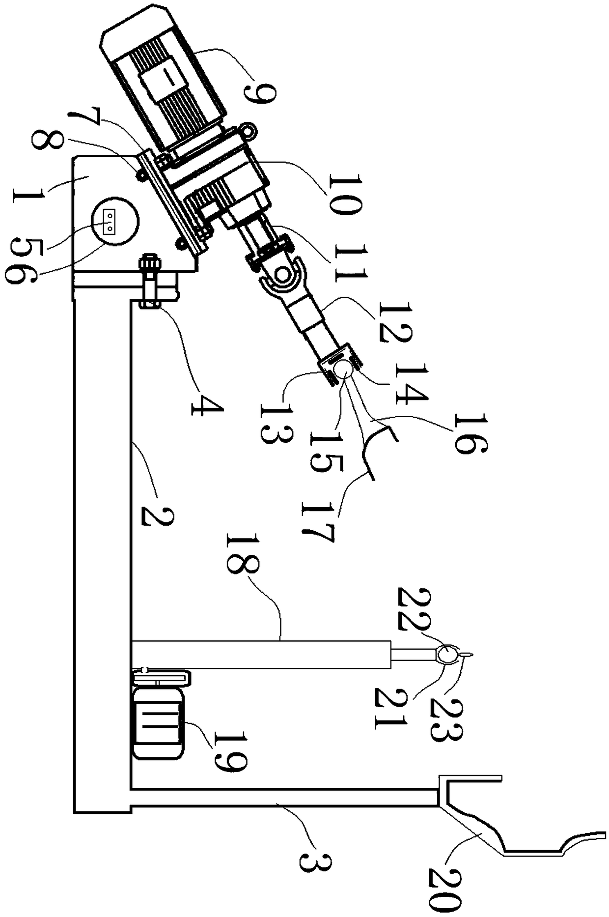
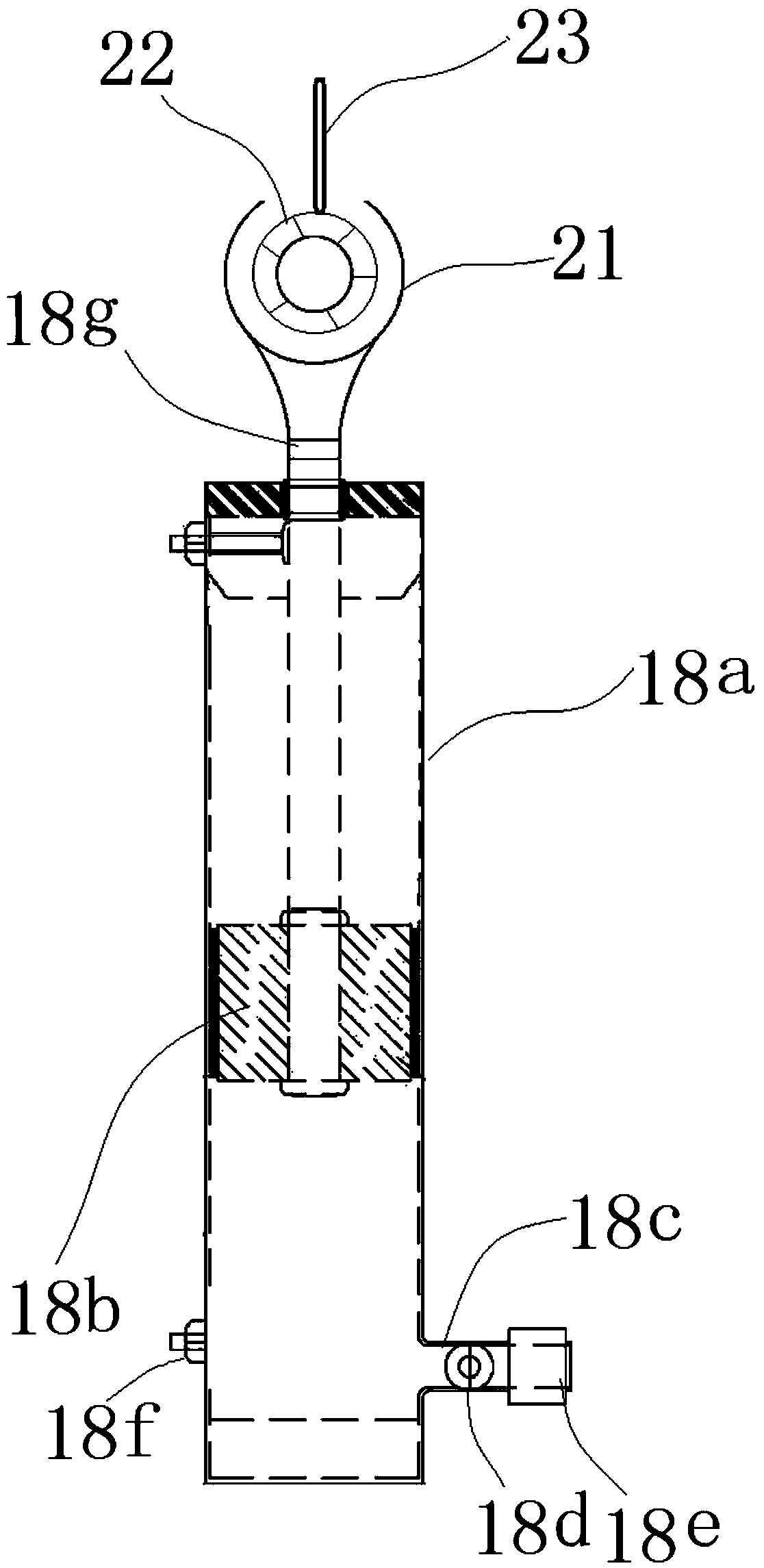
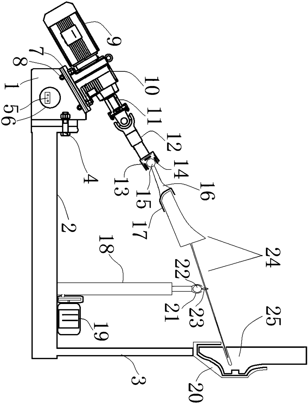
[0042] exist figure 1 In the shown embodiment, the device of the present invention includes a control box 1, a base 2, a support frame 3, a position adjustment member 4, a power interface 5, a main electric board 6, a steering motor 7, a coupling 8, a power motor 9, Gearbox 10, spin anchor rod 11, shaft extension rod 12, joint rod sleeve 13, pressure sensor 14, joint rod end 15, joint rod 16, bracket clamp 17, pneumatic lifting assembly 18, pump motor 19 , link clamping member 20, orientation ball sleeve 21, orientation ball 22, orientation ring 23. One end of the base 2 is connected to the control box 1 through the position adjustment member 4, the other end of the base 2 is vertically provided with a support frame 3 and a link clamp 20 is arranged on the top of the support frame 3, and the inside of the link clamp 20 is chiseled. It is empty and the shape of the gouging groove matches the outer peripheral shape of the end of the linkage rod; the main circuit board 6 is arra...


PUM


Abstract

The invention discloses a device and method for installing a wooden supporting rod into a linkage rod. The device comprises a base, wherein a control box is connected to one end of the base, and a supporting frame is vertically arranged at the other end of the base and a connecting rod clamping and fixing part is arranged at the top of the supporting frame; a main electric board is arranged insidethe control box, and a steering motor is obliquely arranged on the upper part of the control box through connecting parts; a self-screwed bolt of a gearbox is connected to one end of a shaft externalextension rod, and an articulated arm sleeve is arranged at the other end of the shaft external extension rod; an articulated arm end head is arranged at one end of the articulated arm, and a supporting rod clamping and fixing part is arranged at the other end of the articulated arm; a plurality of pressure sensors fix the articulated arm end head at one end of the articulated arm in a wrapped mode, and a pneumatic lifting assembly is arranged on the upper portion, close to the supporting frame, of the base, and a directional ball sleeve is fixed to the upper portion of a top rod of the pneumatic lifting assembly; and the main electric board includes a single chip computer, and a power interface is electrically connected with a solenoid valve, a pump pneumatic motor, the steering motor and a power motor through a voltage conversion circuit correspondingly. The device and method for installing the wooden supporting rod into the linkage rod is completed by using the devices.

Description

technical field [0001] The invention relates to the field of piano manufacturing, in particular to an efficient and accurate device and method for installing a backing rod into a linkage rod. Background technique [0002] Both the linkage rod and the back rod are parts of the piano. During production, it is necessary to install the thin end of the backer rod into the backer rod installation hole of the linkage rod. Traditional technology generally relies on manual operation. It is difficult for workers to grasp the strength and skill of assembly during production. It often happens that the backing bar breaks due to severe uneven stress; in addition, the disclosed Chinese invention CN201610957449.6 discloses a device and method for loading the backing bar into the linkage bar, wherein the device includes a base, installed on The linkage rod positioning mechanism on the base and the jacking mechanism of the backing pole; the jacking mechanism of the backing pole includes a tr...

Claims


Application Information

Patent Timeline
IPC IPC(8): B23P19/04
CPCB23P19/04
Inventor 张庆海
Owner 北京卡丹萨文化艺术有限公司
Learn More