
Device for safely lightening prohibition light of railway signaling machine after all-electronic interlocking system fails

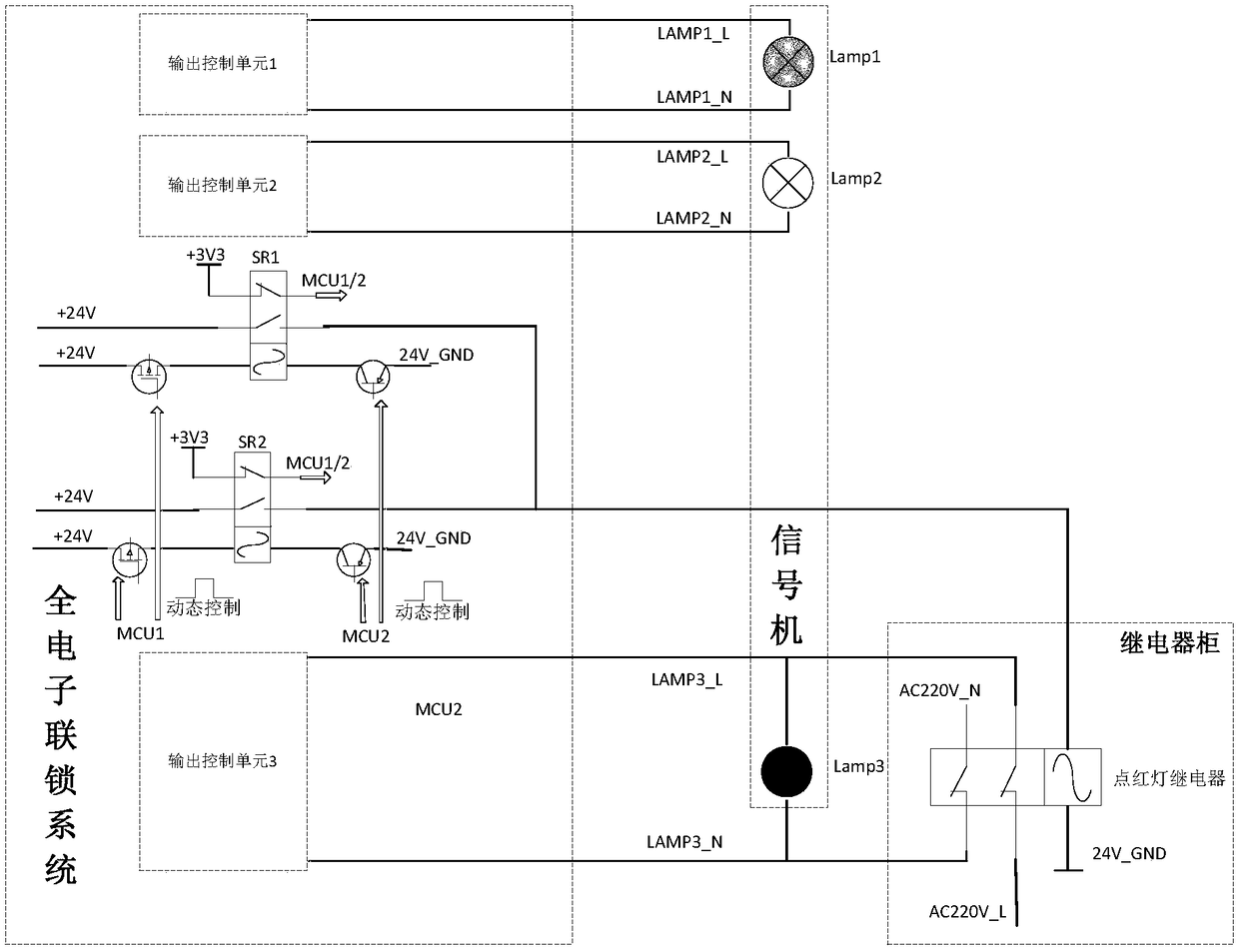
A railway signal and electronic interlocking technology, applied in the field of rail transit, can solve the problems that the system cannot detect, cannot guarantee the +24V power cutoff, and the system fault coverage is low, and achieves the effect of improving availability.

Active Publication Date: 2018-11-09
浙江众合科技股份有限公司
View PDF5 Cites 2 Cited by
  • Summary
  • Abstract
  • Description
  • Claims
  • Application Information

AI Technical Summary

Problems solved by technology

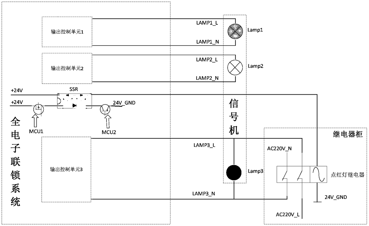
[0006] During normal operation, the solid-state relay SSR is always on, and the function of whether the solid-state relay SSR can be disconnected has not been tested. The fault coverage of the system is low, which is not conducive to the fault judgment of system failure.
[0007] The control circuit of the solid-state relay SSR uses the GPIO pins of MCU1 / MCU2 to control the BJT / MOS tube, thereby controlling the on-off of the solid-state relay SSR. When the short-circuit failure of the BJT / MOS tube occurs, the system cannot detect it. If the BJT / MOS After all the tubes fail, after the full electronic interlock system leads to safety, the external red signal light cannot be lit
[0008] From the above, the design of the red light circuit has not realized the safety function. After the system fails, it cannot guarantee that the +24V power supply can be cut off, that is, it cannot guarantee that the red light signal light will be lit.

Method used


Image

  • Device for safely lightening prohibition light of railway signaling machine after all-electronic interlocking system fails
  • Device for safely lightening prohibition light of railway signaling machine after all-electronic interlocking system fails

Examples


Embodiment Construction

[0017] It should be noted that, in the case of no conflict, the embodiments in the present application and the features in the embodiments can be combined with each other. The present invention will be described in detail below with reference to the accompanying drawings and examples.

[0018] The following will clearly and completely describe the technical solutions in the embodiments of the present invention with reference to the accompanying drawings in the embodiments of the present invention. Obviously, the described embodiments are only some, not all, embodiments of the present invention. The following description of at least one exemplary embodiment is merely illustrative in nature and in no way taken as limiting the invention, its application or uses. Based on the embodiments of the present invention, all other embodiments obtained by persons of ordinary skill in the art without creative efforts fall within the protection scope of the present invention.

[0019] The i...


PUM


Abstract

The invention discloses a device for safely lightening a prohibition light of a railway signaling machine after an all-electronic interlocking system fails. The device includes a red-light lighteningrelay and two safety relays; the normally open and normally closed contacts of the two safety relays keep in mutually exclusive states; the normally open contacts of the two safety relays can be output after merging to control the red-light lightening relay; the normally closed contacts of the two safety relays are independent and used for in real time detecting the output states of the safety relays; when the all-electronic interlocking system operates normally, the safety relays can output power sources, the red-light lightening relay can be sucked up through excitation, and the power supplyof the normally closed contacts can be cut off; and when the all-electronic interlocking system fails, the safety relays can cut off output, the normally closed contact of the red-light lightening relay and a red light of a signaling machine can form a loop, so that the red light can be lightened. The device can in real time detect the working states and abnormal conditions of a red-light lightening circuit so that the situations that circuits cannot be detected due to short circuit failure can be avoided; and the external red-light states cannot be influenced when a single circuit is detected, and the availability of the system can be enhanced.

Description

technical field [0001] The invention relates to the technical field of rail transit, in particular to a railway interlocking control system. Background technique [0002] The signal machine is the key trackside equipment of railway and urban rail transit. In the railway signal system with the ground signal as the main signal, the driver must operate according to the display of the signal machine; in the turnout section of the urban rail transit, the ground is set for the shunting operation. signal machine. The signal colors of the signal machine are divided into red, yellow, green, blue, and moon white. The red light means that trains are not allowed to cross the signal machine, which belongs to the safe state of the railway signal system. After the full electronic interlock system is out of operation due to failure, The system needs to be brought to a safe state and train traffic is prohibited. [0003] Such as figure 1 As shown, after the full electronic interlock syste...

Claims


Application Information

Patent Timeline
Patent Type & Authority Applications(China)
IPC IPC(8): B61L5/18
CPCB61L5/18
Inventor 孙鹏
Owner 浙江众合科技股份有限公司
Learn More