
Connecting rod fatigue test device with high reliability

A fatigue test and reliability technology, applied in the mechanical field, can solve the problems such as failure to design the reliability of the connecting rod fatigue test device, test failure, etc., to ensure continuity and effectiveness, eliminate the risk of damage, and improve reliability. sexual effect

Pending Publication Date: 2018-11-09
HENAN DIESEL ENGINE IND
View PDF3 Cites 0 Cited by
  • Summary
  • Abstract
  • Description
  • Claims
  • Application Information

AI Technical Summary

Problems solved by technology

Due to the alternating cyclic load of tension and pressure, in some fatigue tests, before the fatigue fracture of the connecting rod, the test device itself failed first, resulting in the failure of this test, and the probability of this happening is very high. high
[0004] In some known invention patents and invention patents, such as the connecting rod hydraulic fatigue test system with the application number CN 102393340 A, a connecting rod fatigue test device with the application number CN 104006967 A, and the engine connecting rod with the application number CN 107202694A Rod fatigue durability test device and other patents, related to the connecting rod fatigue test device, mainly expounds the mechanism of connecting rod fatigue loading, and does not carry out targeted design for the reliability of the connecting rod fatigue test device

Method used


Image

  • Connecting rod fatigue test device with high reliability
  • Connecting rod fatigue test device with high reliability

Examples


Embodiment Construction

[0021] The specific embodiment of the present invention will be further described below in conjunction with accompanying drawing:

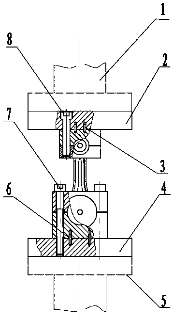
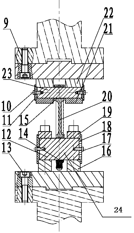
[0022] like figure 1 , 2 As shown, a highly reliable connecting rod fatigue test device, the connecting rod fatigue test device has an adapter flange I2 connected to the lower end of the main drive shaft I1 and an adapter flange connected to the upper end of the main drive shaft II5 II4; the adapter flange I1 and the main transmission shaft I2 are clearance-fitted and solidly connected together; the middle part of the lower end surface of the main transmission shaft I1 has a groove, and the adapter flange I2 is the upper end surface A cylinder with a boss in the middle, and the boss is in clearance fit with the groove on the main transmission shaft I1; there are eight stepped holes evenly distributed along the circumferential direction on the adapter flange I2, and these stepped holes are respectively connected with the main transmission shaft. ...


PUM


Abstract

The invention belongs to the technical field of machines, and provides a diesel engine connecting rod fatigue test device. The connecting rod fatigue test device with high reliability is provided withan adapter flange I connected to the lower end of a main drive shaft I and an adapter flange II connected to the upper end of the main drive shaft II; the adapter flange I and the main drive shaft Iare in clearance fit and are fixedly connected into a whole; the adapter flange II and the main drive shaft II are in clearance fit and are fixedly connected into a whole; the structures of the adapter flange I and the adapter flange II are the same, and the central axis of the adapter flange I, the central axis of the adapter flange II, the central axis of the main drive shaft I and the central axis of the main drive shaft II are located on a same axis; the lower end of the adapter flange I is fixedly connected with a connecting rod small end fixture; the lower end of the adapter flange II isfixedly connected with the main drive shaft II; and the upper end is fixedly connected with the connecting rod large end fixture. According to the invention, the vibration frequency of a connecting rod and the vibration frequency of the connecting rod fatigue test device tend to be consistent, so that the connection between the connecting rod and the test device is firm, and the looseness prevention performance is good.

Description

technical field [0001] The invention belongs to the technical field of machinery, and in particular relates to a diesel engine connecting rod fatigue test device. Background technique [0002] The connecting rod is one of the main power transmission components of the diesel engine. It connects the piston and the crankshaft, drives the crankshaft to rotate and outputs power to the outside. In the actual working process, the connecting rod is subject to cyclically changing gas pressure and inertial force, the stress state is very complicated, and there are countless examples of connecting rod fatigue damage. Therefore, when designing the connecting rod, it is necessary to determine the fatigue strength of the connecting rod through fatigue tests, and then evaluate the reliability and life of the connecting rod. [0003] At present, the hydraulic loading method is mainly used in the industry to carry out the fatigue test of the connecting rod. In the fatigue test of the conne...

Claims


Application Information

Patent Timeline
IPC IPC(8): G01M13/02
CPCG01M13/027
Inventor 王黎明聂志斌季永会
Owner HENAN DIESEL ENGINE IND
Learn More