Rotor structure of asymmetric few-rare-earth-mixed permanent magnet motor

A rare earth permanent magnet motor and rotor structure technology, applied in the magnetic circuit shape/style/structure, magnetic circuit rotating parts, synchronous machines, etc., can solve the problems of irreversible demagnetization, reduction of motor output capacity, permanent magnet self-leakage and other problems , to avoid the decrease of torque performance, improve torque characteristics, and improve motor performance.

Active Publication Date: 2018-11-09
JIANGSU UNIV
View PDF5 Cites 5 Cited by
  • Summary
  • Abstract
  • Description
  • Claims
  • Application Information

AI Technical Summary

Problems solved by technology

Because the magnetic permeability of the iron core material is higher than that of air, the built-in permanent magnet will have a self-leakage phenomenon, the amplitude of the air-gap magnetic base wave will decrease, and the output capacity of the motor will decrease.
At the same time, due to the low coercive force and remanent magnetism of ferrite, irreversible demagnetization is very easy to occur under the action of armature reaction.

Method used


Image

  • Rotor structure of asymmetric few-rare-earth-mixed permanent magnet motor
  • Rotor structure of asymmetric few-rare-earth-mixed permanent magnet motor
  • Rotor structure of asymmetric few-rare-earth-mixed permanent magnet motor

Examples


Embodiment Construction

[0028] The present invention will be further described below in conjunction with the accompanying drawings.

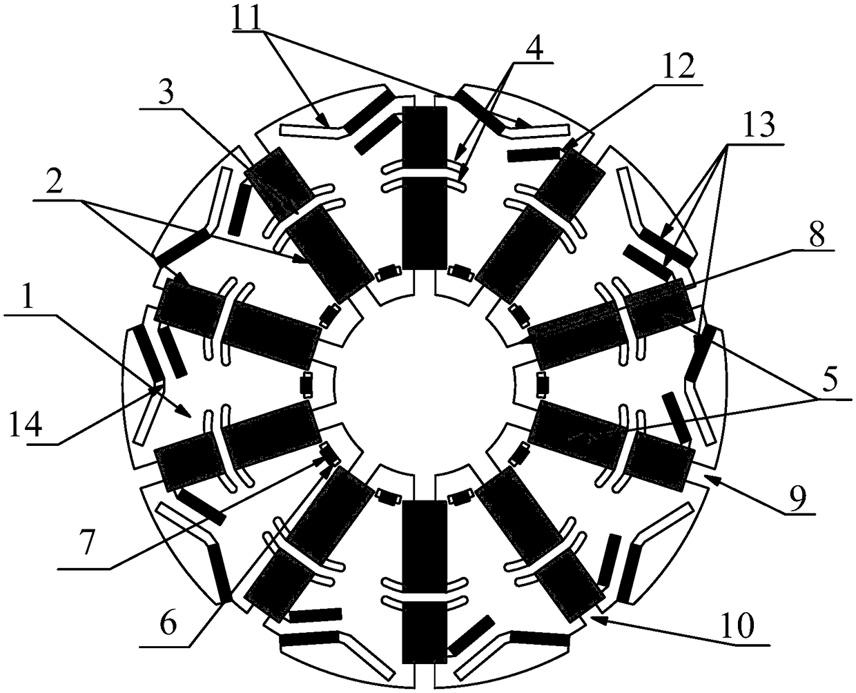
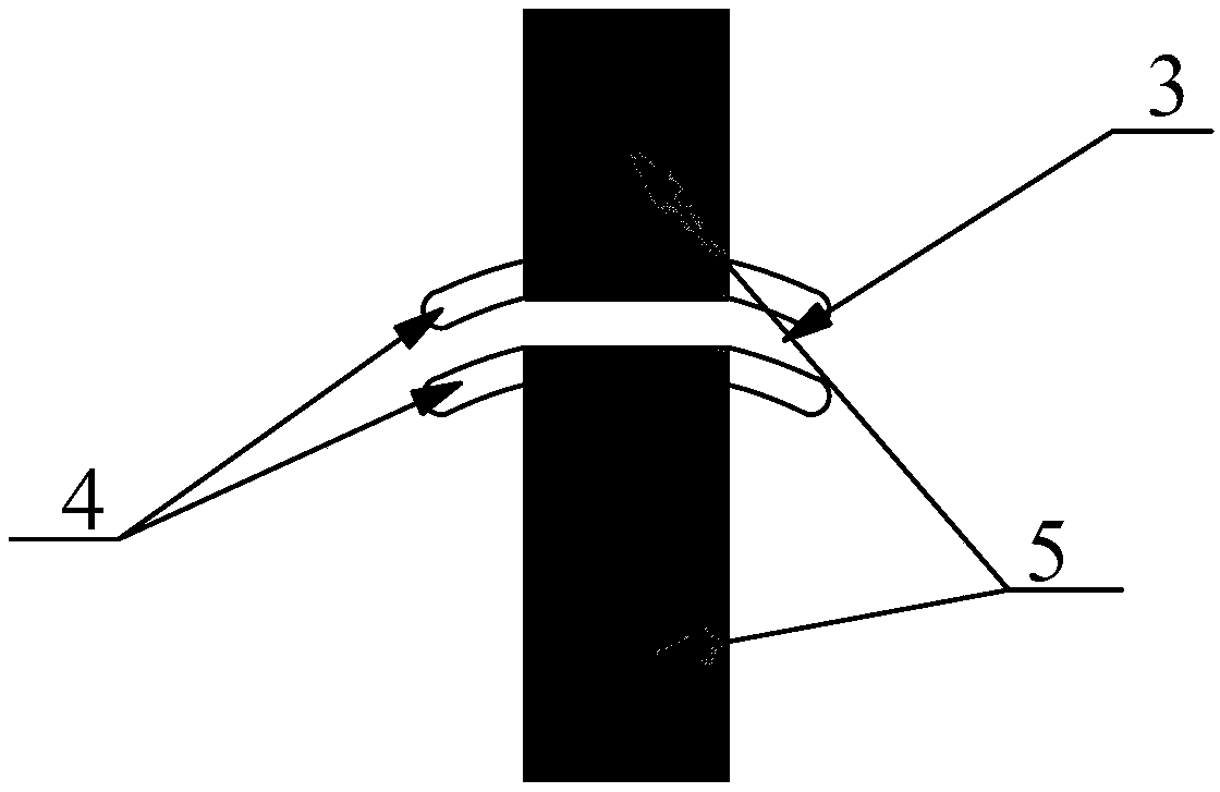
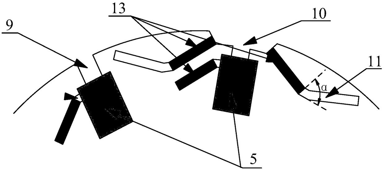
[0029] An asymmetric mixed rare earth permanent magnet motor rotor structure, the rotor is provided with a number of rectangular slots (2) along the vertical circumferential direction, the rectangular slots are divided into upper and lower layers, and rectangular ferrite (5) is embedded in the slots ). The rectangular ferrite (5) is tangentially magnetized, and the upper and lower layers are provided with a magnetic tape (3). Symmetrical horn grooves (4) are provided on the upper and lower sides of the pass-through tape (3). The lower layer of the rectangular groove (2) is provided with a convex groove (6) near the rotating shaft, and the radially magnetized first NdFeB (7) is embedded in the groove. The bottom of the rectangular slot (2) is provided with a first rectangular magnetic isolation slot (8) perpendicular to the axial direction of the rotor. A second rect...


PUM


Abstract

The invention discloses a rotor structure of an asymmetric few-rare-earth-mixed permanent magnet motor. According to the rotor structure, a plurality of rectangular grooves are formed in a rotor in the vertical circumferential direction and are divided into an upper layer and a lower layer; magnetic tapes are formed between the upper layer and the lower layer; rectangular ferrite is embedded in each rectangular groove; symmetrical ox-horn-shaped grooves are formed in the left sides and the right sides of the bottom parts of the upper rectangular grooves and the upper parts of the lower rectangular grooves; convex grooves are formed in the positions, close to a rotating shaft, of the lower layer of the rectangular grooves; rectangular magnetic isolation grooves perpendicular to the axis direction of the rotor are formed in the bottoms of the rectangular grooves; rectangular magnetic isolation grooves and T-shaped magnetic isolation grooves are formed at the joints between the upper layer of the rectangular grooves and air gaps at intervals; V-shaped grooves are symmetrically formed in the left sides and the right sides of the T-shaped magnetic isolation grooves; linear grooves communicated with the rectangular grooves are formed in the left sides of the rectangular grooves; and neodymium-iron-boron permanent magnets are embedded in the sides, close to the ferrite, of the V-shaped grooves and the linear grooves. According to the rotor structure, the material cost of the permanent magnet motor is lowered, the torque characteristics are improved, the iron core and eddy currentloss are reduced, and the efficiency of the motor is improved.

Description

technical field [0001] The invention relates to a rotor structure of a permanent magnet motor, in particular to a rotor structure of an asymmetric mixed rare earth permanent magnet motor, belonging to the technical field of motors. Background technique [0002] Rare earth materials are widely used in industrial production such as motors. However, as non-renewable resources, rare earths have an unstable supply all year round, and their prices fluctuate greatly, which even triggers a rare earth crisis. Therefore, ferrite, which is cheap and easy to obtain raw materials, is used in motors instead of rare earth permanent magnets, which can alleviate the rare earth crisis. Since the magnetic properties of ferrite are much lower than that of rare earth materials, such as NdFeB, it is important to keep the motor performance such as output capacity unchanged through reasonable rotor design. The present invention aims at the above problems, and through the asymmetrical design of the...

Claims


Application Information

Patent Timeline
Patent Type & Authority Applications(China)
IPC IPC(8): H02K1/27H02K21/02
CPCH02K1/27H02K21/028H02K2213/03
Inventor 朱孝勇郑诗玥徐磊华亦峰
Owner JIANGSU UNIV
Why Eureka
Try Eureka