Bidirectional magnetic circuit coupling type magnetic field modulation direct drive motor for electric automobile

A technology for electric vehicles and magnetic field modulation, applied in electric vehicles, magnetic circuit shape/style/structure, motors, etc., can solve the problem that the permanent magnetic field is difficult to adjust low-speed and high-torque characteristics, and achieve low-speed and high-torque characteristics obvious effect

Inactive Publication Date: 2018-11-09
HARBIN UNIV OF SCI & TECH
View PDF5 Cites 2 Cited by
  • Summary
  • Abstract
  • Description
  • Claims
  • Application Information

AI Technical Summary

Problems solved by technology

[0004] The present invention aims to solve the shortcomings of the existing permanent magnet motors used in electric vehicles, which are difficult to adjust the permanent magnet magnetic field and have insufficient low-speed an...

Method used


Image

  • Bidirectional magnetic circuit coupling type magnetic field modulation direct drive motor for electric automobile
  • Bidirectional magnetic circuit coupling type magnetic field modulation direct drive motor for electric automobile
  • Bidirectional magnetic circuit coupling type magnetic field modulation direct drive motor for electric automobile

Examples


specific Embodiment approach 1

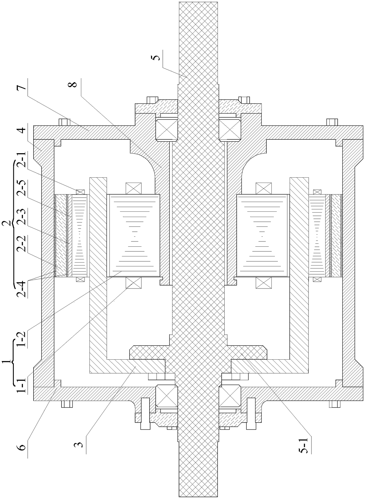
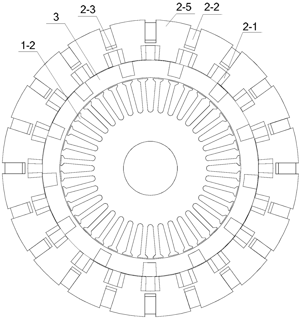
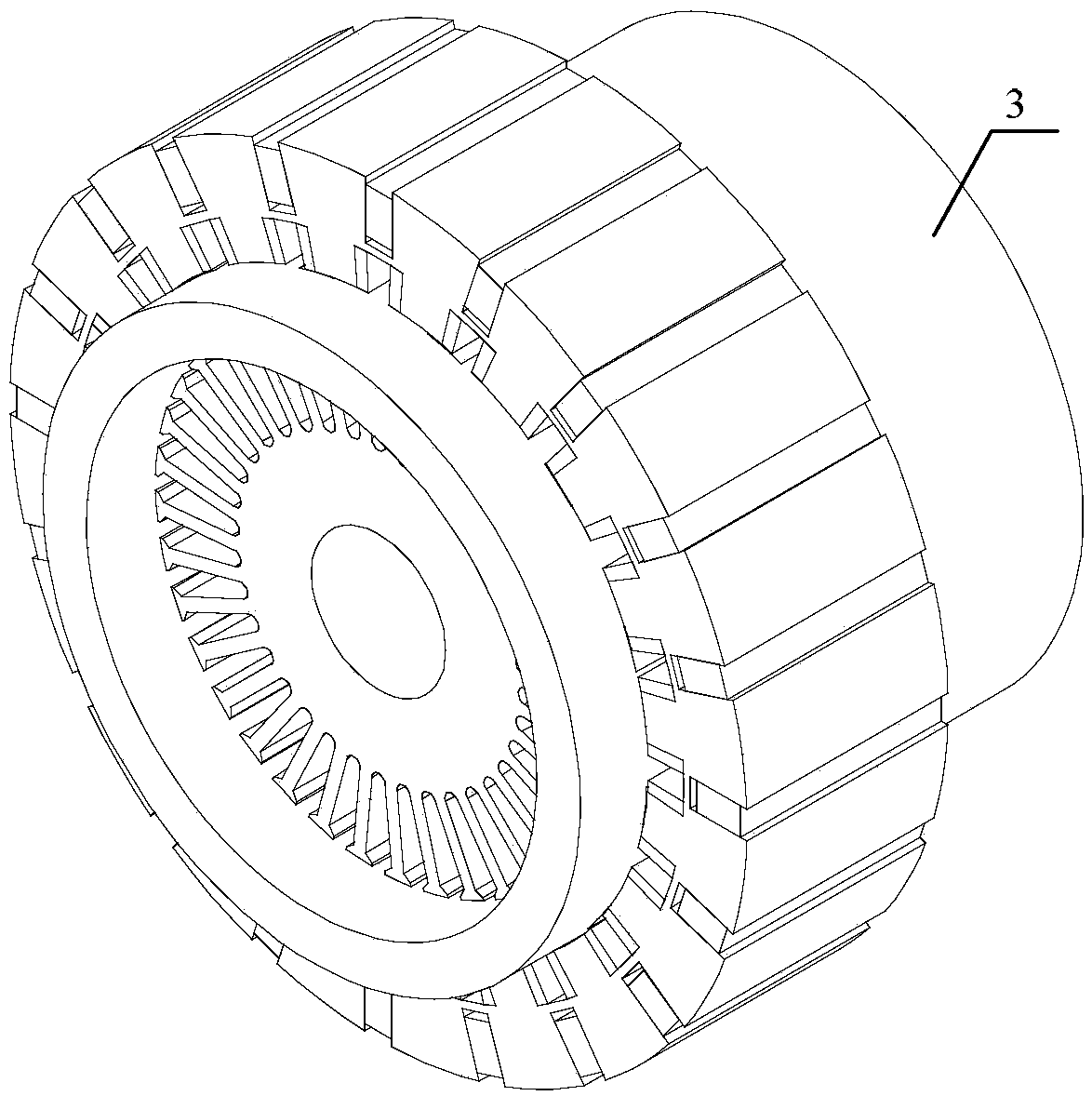
[0031] Specific implementation mode one: refer to Figures 1 to 12 Describe this embodiment in detail. The two-way magnetic circuit coupled magnetic field modulation direct drive motor for electric vehicles described in this embodiment includes: an inner stator 1, an outer stator 2, a cup-shaped rotor 3, a casing 4 and an output shaft 5;

[0032] The casing 4 is a cylindrical structure, the two ends of the casing 4 are respectively blocked by the left end cover 6 and the right end cover 7, and the centers of the left end cover 6 and the right end cover 7 are both provided with through holes, and the output shaft 5 passes through the two end covers The through hole on the top runs through both ends of the casing 4, so that the middle section of the output shaft 5 is located inside the casing 4, and the two ends of the output shaft 5 are positioned outside the casing 4. Between the left end cover 6 and the output shaft 5, between the right end cover 7 and the output shaft 5, all...


PUM


Abstract

The invention discloses a bidirectional magnetic circuit coupling type magnetic field modulation direct drive motor for an electric automobile, and relates to the field of hybrid excitation of magnetic field modulation type composite motors. The bidirectional magnetic circuit coupling type magnetic field modulation direct drive motor solves the problems that the permanent magnetic field of an existing permanent magnet motor for an electric automobile is difficult to adjust and insufficient in low-speed and high-torque characteristic. According to the bidirectional magnetic circuit coupling type magnetic field modulation direct drive motor, 2n outer stator teeth are uniformly arranged on the inner circumferential surface of an outer stator core in the circumferential direction, an outer stator direct-current exciting winding is wound around each outer stator tooth, the current directions of every two adjacent outer stator direct-current exciting windings are opposite, 2n permanent magnet grooves are uniformly formed in the outer circumferential surface of the outer stator core in the circumferential direction, a permanent magnet is arranged in each permanent magnet groove, magneticisolation bridges are arranged on the two sides, facing groove bottoms and groove openings, of the permanent magnets, the part, corresponding to the bottoms of the permanent magnet grooves, of the outer stator core is served as a magnetic conduction bridge, the magnetizing directions of every two adjacent permanent magnets are opposite, the direction of the magnetic force lines of the permanent magnets is the tangential direction of the outer stator core, and the direction of the magnetic force lines of the outer stator direct-current exciting windings is the radial direction of the outer stator core.

Description

technical field [0001] The invention belongs to the field of hybrid excitation of a magnetic field modulation compound motor. Background technique [0002] As an important measure to solve the energy crisis in contemporary society, electric vehicles play a pivotal role in the field of automobile development. How to design high-performance permanent magnet synchronous motors for electric vehicles has become a hot issue for domestic and foreign experts and scholars. At present, there are still some problems with permanent magnet motors for electric vehicles, such as: the permanent magnet magnetic field is difficult to adjust, which makes it difficult for electric vehicles to obtain a wider speed regulation range when running at constant power; the low-speed and high-torque characteristics of the motor are not obvious, It is necessary to install a deceleration device inside the car, which increases the overall space occupied by the car motor. [0003] The magnetic field modul...

Claims


Application Information

Patent Timeline
IPC IPC(8): H02K16/04H02K1/14H02K1/17
CPCH02K1/14H02K1/17H02K16/04H02K2213/03Y02T10/64
Inventor 谢颖张晓明邳成华邦杰
Owner HARBIN UNIV OF SCI & TECH
Why Eureka
Try Eureka