A decorative panel

A technology for decorative panels and decorative layers, which is applied in the directions of decorations, decorative arts, special decorative structures, etc., and can solve the problem of only using panel functions

Inactive Publication Date: 2018-11-09
TRESPA INT
View PDF9 Cites 0 Cited by
  • Summary
  • Abstract
  • Description
  • Claims
  • Application Information

AI Technical Summary

Problems solved by technology

This means that the function of these panels is only for construction and aesthetic purposes

Method used


Image

  • A decorative panel
  • A decorative panel
  • A decorative panel

Examples


example 1

[0079] Example 1: Fabrication of an induction charger panel.

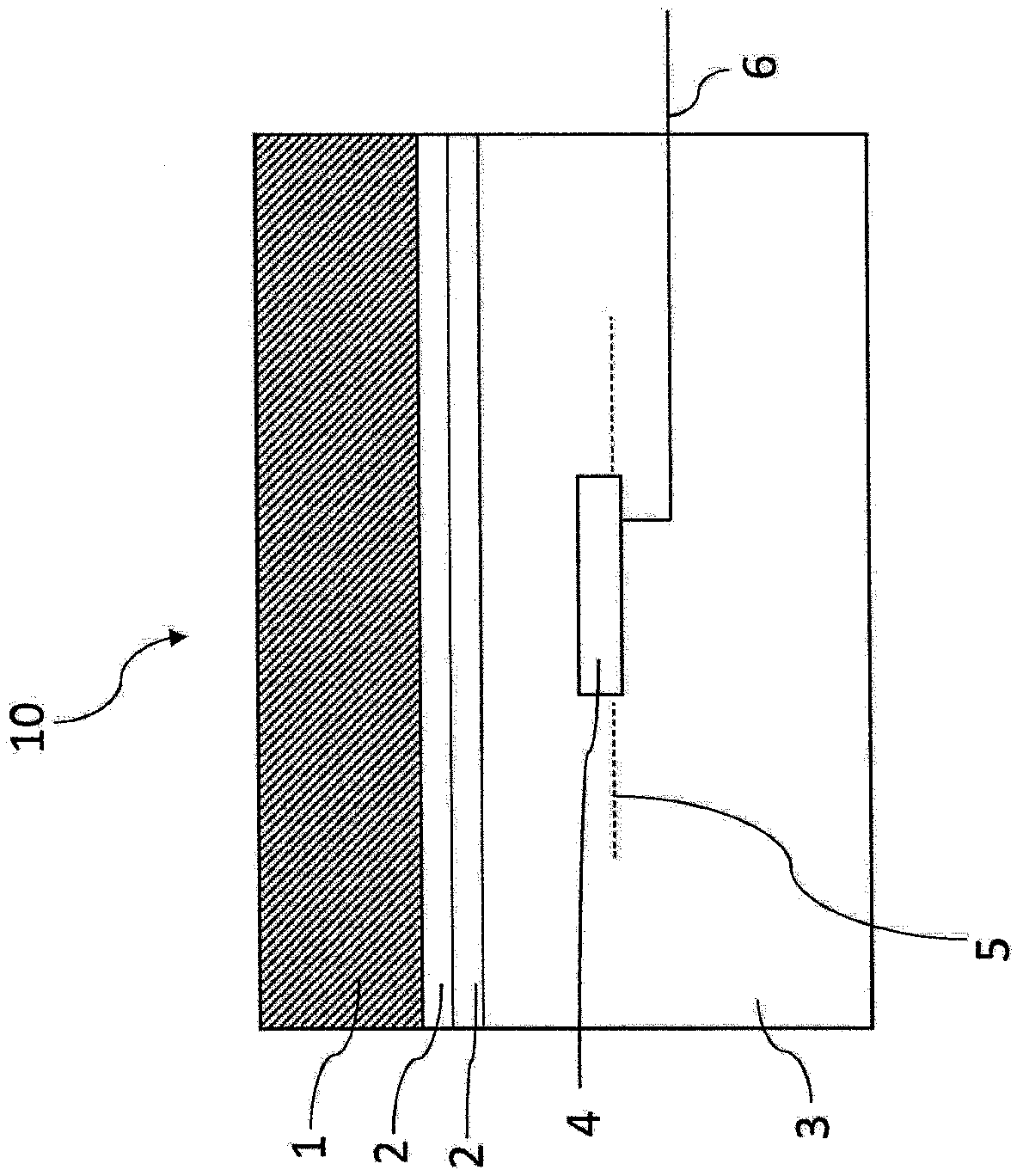
[0080] According to this example, a commercial induction charger of the type ZENS Single Wireless Charger (#ZESC05B / 00) is heat pressed into the trim panel. The inductive charger is placed in a recess made in the prepreg, and the recess with the inductive charger is completely covered with a layer of resin-impregnated paper. On top of the resin-impregnated layer, a decorative layer is applied as the outermost surface layer. The composite thus obtained was pressed at 160° C. and 20 bar until curing of the thermosetting resin was achieved. The induction charger in the final panel receives power via a cable that connects the induction charger to a standard household electrical outlet. The phone is placed on the outermost surface of the panel, the panel's inductive charger is activated by an external power source, and the phone is charged wirelessly.

example 2

[0081] Example 2: Fabrication of an induction charger panel.

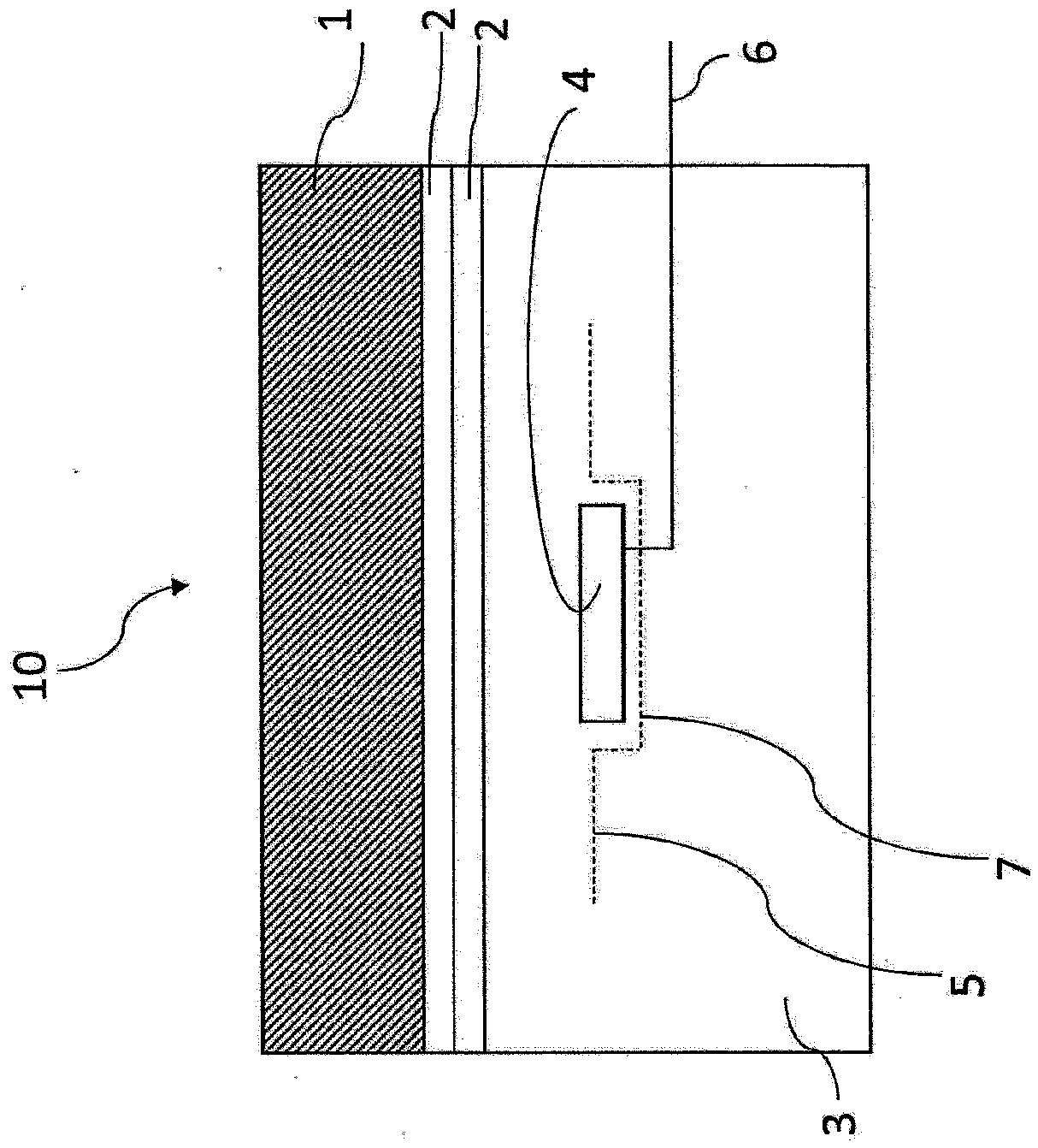
[0082] A single wired induction coil of the type found in the ZENS 20 single wireless charger is placed in a recess made in the prepreg and 5 sheets of resin impregnated paper are placed on top of the coil to obtain a package containing the prepreg and Composite of induction coils completely covered with resin impregnated paper. The induction coil is thus seamlessly integrated into the compound. On top of the thus positioned resin-impregnated paper a decorative layer is placed and the assembly is pressed at 160° C. and 70 bar until curing of the thermosetting resin is achieved. The cables from the integrated coils of the panels thus obtained were connected to an external power source. The phone is placed on the outermost surface of the panel, the panel's inductive charger is activated, and the phone is charged wirelessly.

example 3

[0083] Example 3: Fabrication of an induction charger panel.

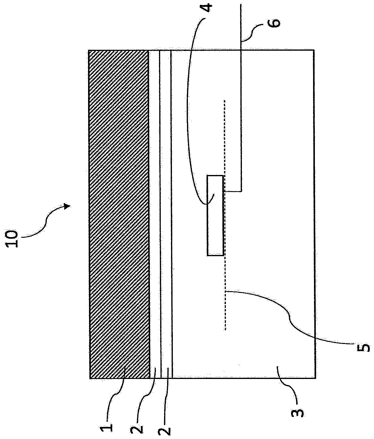
[0084] A single wired induction coil of the similar type found in the ZENS 20 single wireless charger is placed in a recess formed in the resin impregnated paper stack, then 5 sheets of resin impregnated paper without the recess are added on top of the coil so positioned, thus Obtain a composite that includes resin-impregnated paper and a fully integrated induction coil. A decorative layer is placed on top of the thus positioned resin-impregnated paper. The assembly thus obtained was pressed at 160° C. and 70 bar until curing of the thermosetting resin was achieved. The cables from the integrated coils of the panels thus obtained were connected to an external power source. The phone is placed on the outermost surface of the panel, the panel's inductive charger is activated, and the phone is charged wirelessly.


PUM

PropertyMeasurementUnit
thicknessaaaaaaaaaa

Abstract

The present invention relates to a decorative panel, comprising a core layer provided with a decor layer, said decor layer comprising a substrate layer provided with at least one coating, wherein within said decorative panel at least one induction coil is located. The present invention furthermore relates to the use of such a decorative panel in indoor and / or outdoor furniture and in interior and / or exterior decoration.

Description

technical field [0001] The invention relates to a decorative panel comprising a core layer provided with a decorative layer, wherein the decorative layer comprises a base layer provided with at least one coating. Furthermore, the invention relates to the use of such panels. Background technique [0002] Decorative high pressure compact laminate panels manufactured by the applicant are known for outdoor applications. Such laminated panels consist of layers of wood-based fibers (paper and / or wood) impregnated with a thermosetting resin and a surface layer on one or both sides with a decorative color or pattern. A clear topcoat is added to the surface layer and cured to enhance weather and light protection. The components are bonded together under the simultaneous application of heat and high unit pressure to obtain a uniform non-porous material with increased density and an overall decorative surface. These panels have been disclosed, inter alia, in US Patent No. 4,801,495,...

Claims


Application Information

Patent Timeline
Patent Type & Authority Applications(China)
IPC IPC(8): B32B21/08B32B29/00B32B29/02B32B3/26B32B3/30B44C5/04B32B23/06H01F38/14H02J7/02B32B5/02B32B5/22B32B21/02B32B21/06B32B21/10B32B23/08B32B23/10B32B27/10B32B27/12B32B27/36
CPCB32B5/022B32B5/024B32B5/22B32B21/02B32B21/06B32B21/08B32B21/10B32B23/06B32B23/08B32B23/10B32B27/10B32B27/12B32B27/36B32B29/005B32B29/02B32B3/08B32B3/266B32B3/30B44C5/0484H01F38/14B32B2255/02B32B2255/12B32B2260/028B32B2262/02B32B2262/062B32B2262/067B32B2262/101B32B2262/103B32B2262/105B32B2262/106B32B2307/208B32B2451/00B32B2457/00B32B2479/00B32B2607/00B32B2307/212H02J7/0042H02J50/10B44C5/04H02J50/70H01F27/36H01F27/366B32B7/12B32B29/06B32B2260/046
Inventor 贝吉塔·凯塔琳娜·夏洛特·凯基兰德
Owner TRESPA INT
Why Eureka
Try Eureka