Unlock instant, AI-driven research and patent intelligence for your innovation.

Concave can end

A can end, crimp technology, applied in cans/barrels/barrels, other household utensils, transportation and packaging, etc., to improve cleanliness, save weight, and reduce shell weight

Active Publication Date: 2018-11-09
CROWN PACKAGING TECH
View PDF14 Cites 0 Cited by
  • Summary
  • Abstract
  • Description
  • Claims
  • Application Information

AI Technical Summary

Problems solved by technology

Therefore, the aerosol can end is usually formed by a press with a domed mold center piece against which the material is usually molded, without which the final product would have a commercially unacceptable amount of wrinkling

Method used


Image

  • Concave can end
  • Concave can end
  • Concave can end

Examples


Embodiment Construction

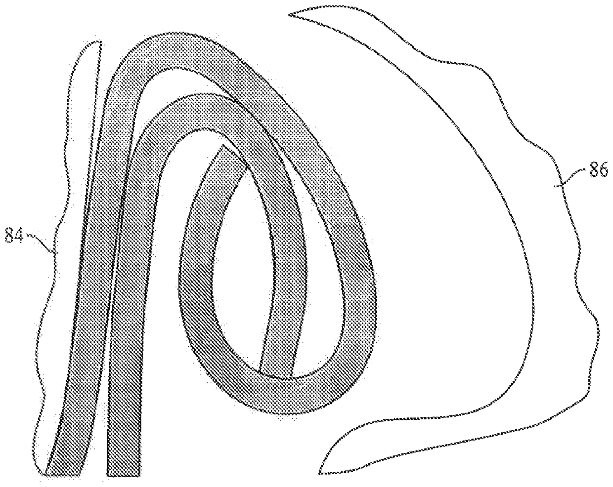
[0076] Referring to the drawings, a container package such as package 5 includes a beverage can end 10 and a can body 50 . End 10 is in its unsewn configuration (for example, as Figure 15 shown in ) including a curled portion 12 at its outer periphery, a wall 14 extending radially inward and downward from the curled portion 12, sometimes referred to as a chuck wall, and a smoothly extending Inwardly or concavely curved panel 16 . Seamed ends and some components are indicated by use of superscript designations, eg, seamed end 10' and seamed chuck wall 14'. The unsewn end and some of its components are denoted by reference numerals without superscripts, eg, the unsewn end 10 and its chuck wall 14 . As described below, some components of the end portion 10 are omitted for convenience of illustration, and reference numerals 8 and 9 are used to denote shells before they are finally formed into the end portion 10 .

[0077] The tear-away panel is formed by a score 18 which, afte...


PUM

PropertyMeasurementUnit
Diameteraaaaaaaaaa
Diameteraaaaaaaaaa
Radiusaaaaaaaaaa

Abstract

A container can end (10) includes a dome shaped center panel (16), concave on a pull tab (30) mounting side, and may forgo a peripheral reinforcing bead around the center panel. The tab (30) may alsobe curved. Tooling for forming the end and a corresponding method are provided.

Description

[0001] Cross References to Related Applications [0002] This application claims the benefit of US Provisional Application Serial No. 62 / 301128, filed February 29, 2016, the disclosure of which is hereby incorporated by reference as if set forth in its entirety herein. Background technique [0003] Commercial cans, such as those used to contain food, beverages, or products dispensed as aerosols, may be of "two-piece" or "three-piece" construction. Conventional two-piece tanks include a single-piece tank body formed by a deep drawing and thinning process, also known as deep drawing and wall thinning ("DWI"). The DWI process draws a metal blank into the shape of a cup, then pushes the cup through a series of rings that thin the walls to their desired thickness and length. At the end of the thinning process, the can is pushed into the arching station to form the bottom dome of the integral can body. The open can end is then trimmed, necked in diameter, and deformed outward to ...

Claims


Application Information

Patent Timeline
IPC IPC(8): B65D17/00B21D22/22B21D22/30B21D51/44B65D6/30
CPCB21D22/22B21D51/44B65D7/36B65D17/4012B21D51/2623B21D51/32B21D51/2661B21D51/383B65D1/165B65D1/20B65D17/02B65D2517/0014
Inventor B.马提恩T.克拉克C.P.拉姆齐
Owner CROWN PACKAGING TECH