
Multipiece wiring board, wiring board, and method for manufacturing multipiece wiring board

A wiring substrate and multi-piece technology, which is applied in the manufacturing field of multi-piece wiring substrates, can solve the problem of small width of the dividing groove, and achieve the effects of suppressing burrs and chipping, high dimensional accuracy, and good dividing ease.

Active Publication Date: 2018-11-09
KYOCERA CORP
View PDF5 Cites 0 Cited by
  • Summary
  • Abstract
  • Description
  • Claims
  • Application Information

AI Technical Summary

Problems solved by technology

That is, by forming through-holes for the positional deviation of the dividing grooves in the upper and lower surfaces, it is possible to make a multi-piece wiring board that is not easily affected by the positional deviation of the dividing grooves. In the case of a wiring board on which through holes are formed, in the processing of the dividing grooves by laser, the width of the dividing grooves is smaller than that of the conventional dividing grooves formed mechanically by using a mold or the like. Compared with a mother board in a wiring board region with a through-hole, a mother board in which a wiring board region without a through-hole is arranged has the problem that, when the position of the dividing groove is shifted, etc., the wiring board region Difficult to segment the corners of

Method used


Image

  • Multipiece wiring board, wiring board, and method for manufacturing multipiece wiring board
  • Multipiece wiring board, wiring board, and method for manufacturing multipiece wiring board
  • Multipiece wiring board, wiring board, and method for manufacturing multipiece wiring board

Examples


Embodiment Construction

[0025] A multi-piece wiring board, a wiring board, and a method for manufacturing a multi-piece wiring board according to the present invention will be described with reference to the drawings.

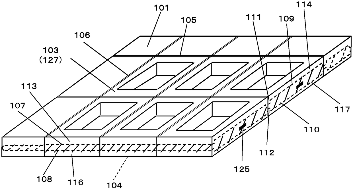
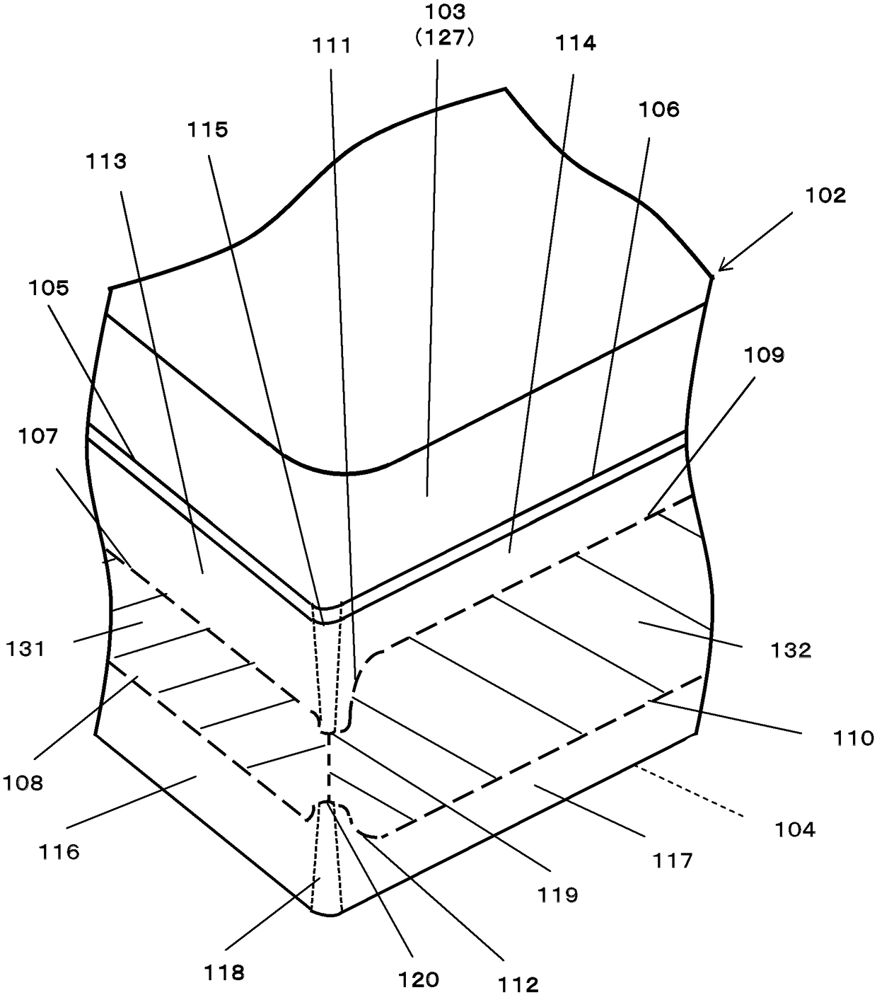
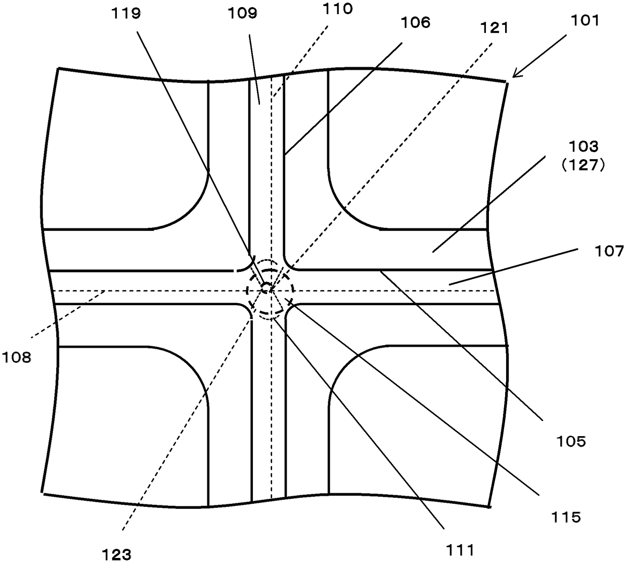
[0026] exist Figure 1 to Figure 8 Among them, 101 is the motherboard, 102 is the wiring substrate, 103 is the first main surface, 104 is the second main surface, 105 is one side, 106 is the other side, 107 is the first dividing groove, 108 is the second Dividing groove, 109 is the third dividing groove, 110 is the fourth dividing groove, 111 is the first curved part, 112 is the second curved part, 113 is the first side, 114 is the second side, 115 is the first curved surface, 116 is the third side, 117 is the fourth side, 118 is the second curved surface, 119 is the first bottom, 120 is the second bottom, 121 is the first intersection, 122 is the second intersection, 123 is the first imaginary circle, 124 is a second imaginary circle, 125 is a wiring conductor for connection, 126 is...


PUM


Abstract

A multipiece wiring board is provided with a motherboard which includes a first main surface and a second main surface opposing the first main surface, and on which a plurality of wiring board regionsare arranged. The motherboard includes dividing grooves disposed on the first main surface and the second main surface along the boundaries of the wiring board regions. The dividing grooves include:a first dividing groove disposed along one side of the wiring board regions on the first main surface; a second dividing groove disposed on the second main surface so as to oppose the first dividing groove; a third dividing groove disposed along another side of the wiring board regions on the first main surface; and a fourth dividing groove disposed on the second main surface so as to oppose the third dividing groove. The depth of the first dividing groove and the depth of the second dividing groove are greater than the depth of the third dividing groove and the depth of the fourth dividing groove. The multipiece wiring board includes a first curved portion in which the depth of the third dividing groove is gradually increased, and a second curved portion in which the depth of the fourth dividing groove is gradually increased, toward a corner of the wiring board regions.

Description

technical field [0001] The present invention relates to a multi-piece wiring board, a wiring board, and a method for manufacturing a multi-piece wiring board in which a plurality of wiring board regions having electronic component mounting portions are arranged vertically and horizontally on a mother board. Background technique [0002] Conventionally, there is known a multi-piece wiring board in which a plurality of wiring board regions are arranged vertically and horizontally on a mother board. Separation grooves are formed on the main surface such as the upper surface of the mother substrate along the boundary of the wiring board region. The mother substrate is broken by applying bending stress to the mother substrate across the division groove, and is divided into individual wiring substrates. The division grooves are formed, for example, by using a dicing blade or the like to make notches at a predetermined depth on the upper surface and the lower surface of the unfire...

Claims


Application Information

Patent Timeline
IPC IPC(8): H05K1/02H01L23/12H05K3/00
CPCH01L21/4846H01L23/13H01L23/498H05K3/0052H05K3/4629H05K2201/0909H05K3/0026H05K3/0097H01L23/544H03B5/326H03H3/02H03H3/08H03H9/02897H03H9/058H03H9/19H05K1/02H05K1/0284H05K1/0298H05K1/03H05K1/119H05K3/00H05K3/0029H05K2203/107
Inventor 鬼塚善友
Owner KYOCERA CORP
Learn More