An alignment robot gripper for shearing plates

A robot hand, Chinese-style technology, applied in the direction of the manipulator, the attachment of the shearing machine, the shearing device, etc., can solve the problems of easy clamping of thin plates, strong clamping pressure, affecting the clamping force of sheet metal parts, etc. The effect of flat structure, reduced assembly workload, and stable strength

Active Publication Date: 2019-12-10
SHANGHAI LEADERSOFT INFORMATION TECH CO LTD
View PDF5 Cites 0 Cited by
  • Summary
  • Abstract
  • Description
  • Claims
  • Application Information

AI Technical Summary

Problems solved by technology

[0003] The sheet metal grasping and clamping devices used in the traditional shearing processing industry generally have the following defects: 1. There is no connecting rod mechanism inside the ordinary cylinder, and the clamping force on the sheet metal parts is very small, and it fluctuates with the air source. The clamping force will also change, it is very unstable, it is easy to affect the clamping force of the sheet metal parts, and it is easy to cause excessive pressure or air pressure; 2. It cannot be automatically centered; 3. It cannot be clamped in parallel, and the clamping pressure is strong. It is easy to clamp the thin plate; 4. There are very few products on the market that can clamp the sheet metal parts in both directions. Most of the sheet metal clamps can only clamp the workpiece in one direction, which is difficult to meet the needs of robots for flexible shearing. Production requirements; 5. The movement direction of the cylinder is almost parallel to the clamping direction, resulting in a large volume of the gripper, which requires a large space when grabbing the plate, which is not conducive to the grasping of the plate

Method used


Image

  • An alignment robot gripper for shearing plates
  • An alignment robot gripper for shearing plates
  • An alignment robot gripper for shearing plates

Examples


Embodiment Construction

[0026] The present invention will be described in detail below with reference to the drawings and specific embodiments. This embodiment is implemented on the premise of the technical solution of the present invention, and a detailed implementation mode and specific operation process are given, but the protection scope of the present invention is not limited to the following embodiments.

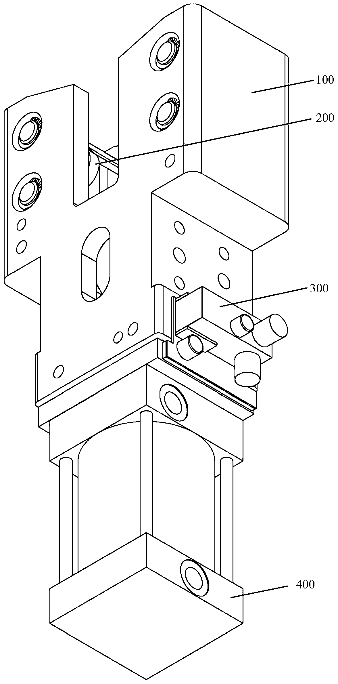
[0027] Such as Figure 1 ~ Figure 3 As shown, this embodiment provides a chute-type robot gripper for shearing plates, which includes a housing 100, a connecting rod clamping module 200, a position sensing module 300, and a driving module 400. The housing 100 is provided with interconnected connections. The rod clamping module 200 and the position sensing module 300 are connected to the driving module 400 at the lower end of the housing 100.

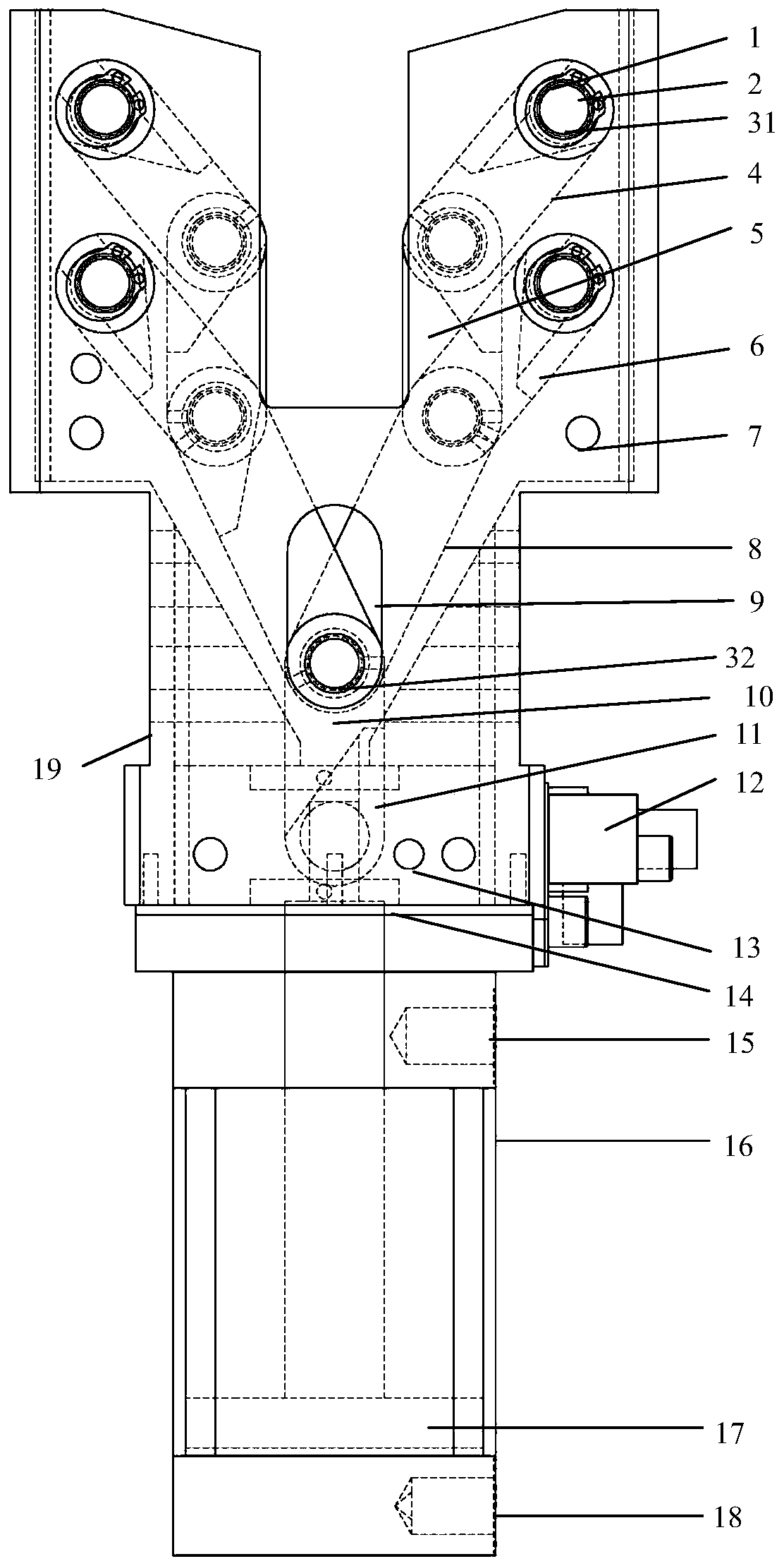
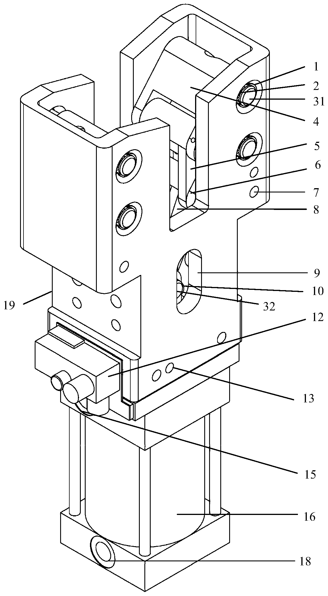
[0028] The upper end of the housing 100 has a symmetrical clamping structure, with pin holes 1 and sliding grooves 9, and eight pin holes 1 are arranged ve...


PUM


Abstract

The invention relates to a centering type robot paw for a shear plate. The centering type robot paw comprises a housing, a connecting rod clamping module, a position sensing module and a driving module; the connecting rod clamping module and the position sensing module which are connected with each other are arranged inside the housing; the lower end of the housing is connected with the driving module, wherein the upper end of the housing is of a symmetric clamping structure and is provided with a pinhole and a sliding chute; and the connecting rod clamping module is connected with the housingthrough the pinhole and the sliding chute. Compared with the prior art, the centering type clamping module of the centering type robot paw provided by the invention adopts the pinhole, a pin shaft and a clamping structure for a connecting rod; a cylinder is used for pushing the connecting rod by virtue of a slider so as to realize clamping or releasing; a force enhancing effect is achieved; relatively large clamping force can be generated by virtue of relatively small working air pressure; the force strength is stable; and the centering type robot paw meets the requirements of production of flexible shear plates of robots.

Description

Technical field [0001] The invention relates to an industrial vision robot hand claw, in particular to a centering robot hand claw for shearing plates. Background technique [0002] At present, the sheet metal grabbing methods used in the shearing operation mainly include vacuum chucks, electromagnetic chucks, and vacuum and electromagnetic composite chucks. Although the electromagnetic chuck has great suction power, it is heavy and expensive. The vacuum suction cup is light, relatively cheap, and widely used. The vacuum and electromagnetic composite chuck has a complex structure, needs to be customized, has a large weight and a high price. With the development of flexibility in shearing operations, robotic flexible shears are also on the agenda. [0003] The sheet metal grabbing and clamping devices used in the traditional shearing industry generally have the following defects: 1. There is no linkage mechanism inside the ordinary cylinder, and the clamping force on the sheet me...

Claims


Application Information

Patent Timeline
Patent Type & Authority Patents(China)
IPC IPC(8): B23D33/02B23D15/06B25J15/02
CPCB23D15/06B23D33/02B25J15/02
Inventor 刘方湖
Owner SHANGHAI LEADERSOFT INFORMATION TECH CO LTD
Why Eureka
Try Eureka