A chute-type robot gripper for shearing

A robot hand and chute technology, applied in the directions of manipulators, accessories of shearing machines, shearing devices, etc., can solve the problems of parallel clamping, easy clamping of thin plates, strong clamping pressure, etc., and achieve the cylinder action direction and The effect of vertical clamping, flat gripper structure, and fewer parts

Active Publication Date: 2020-01-03
SHANGHAI LEADERSOFT INFORMATION TECH CO LTD
View PDF7 Cites 0 Cited by
  • Summary
  • Abstract
  • Description
  • Claims
  • Application Information

AI Technical Summary

Problems solved by technology

[0003] The sheet metal grasping and clamping devices used in the traditional shearing processing industry generally have the following defects: 1. There is no connecting rod mechanism inside the ordinary cylinder, and the clamping force on the sheet metal parts is very small, and it fluctuates with the air source. The clamping force will also change, it is very unstable, it is easy to affect the clamping force of the sheet metal parts, and it is easy to cause excessive pressure or air pressure; 2. It cannot be automatically centered; 3. It cannot be clamped in parallel, and the clamping pressure is strong. It is easy to clamp the thin plate; 4. There are very few products on the market that can clamp the sheet metal parts in both directions. Most of the sheet metal clamps can only clamp the workpiece in one direction, which is difficult to meet the needs of robots for flexible shearing. Production requirements; 5. The movement direction of the cylinder is almost parallel to the clamping direction, resulting in a large volume of the gripper, which requires a large space when grabbing the plate, which is not conducive to the grasping of the plate

Method used


Image

  • A chute-type robot gripper for shearing
  • A chute-type robot gripper for shearing
  • A chute-type robot gripper for shearing

Examples


Embodiment Construction

[0024] The present invention will be described in detail below in conjunction with the accompanying drawings and specific embodiments. This embodiment is carried out on the premise of the technical solution of the present invention, and detailed implementation and specific operation process are given, but the protection scope of the present invention is not limited to the following embodiments.

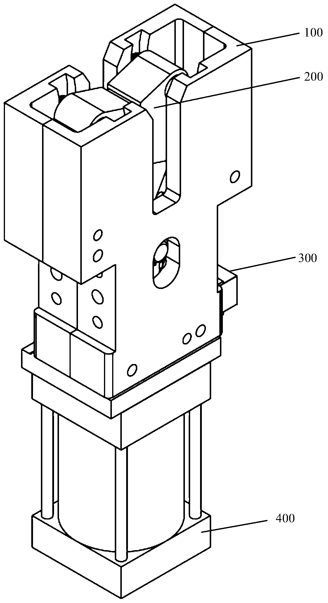
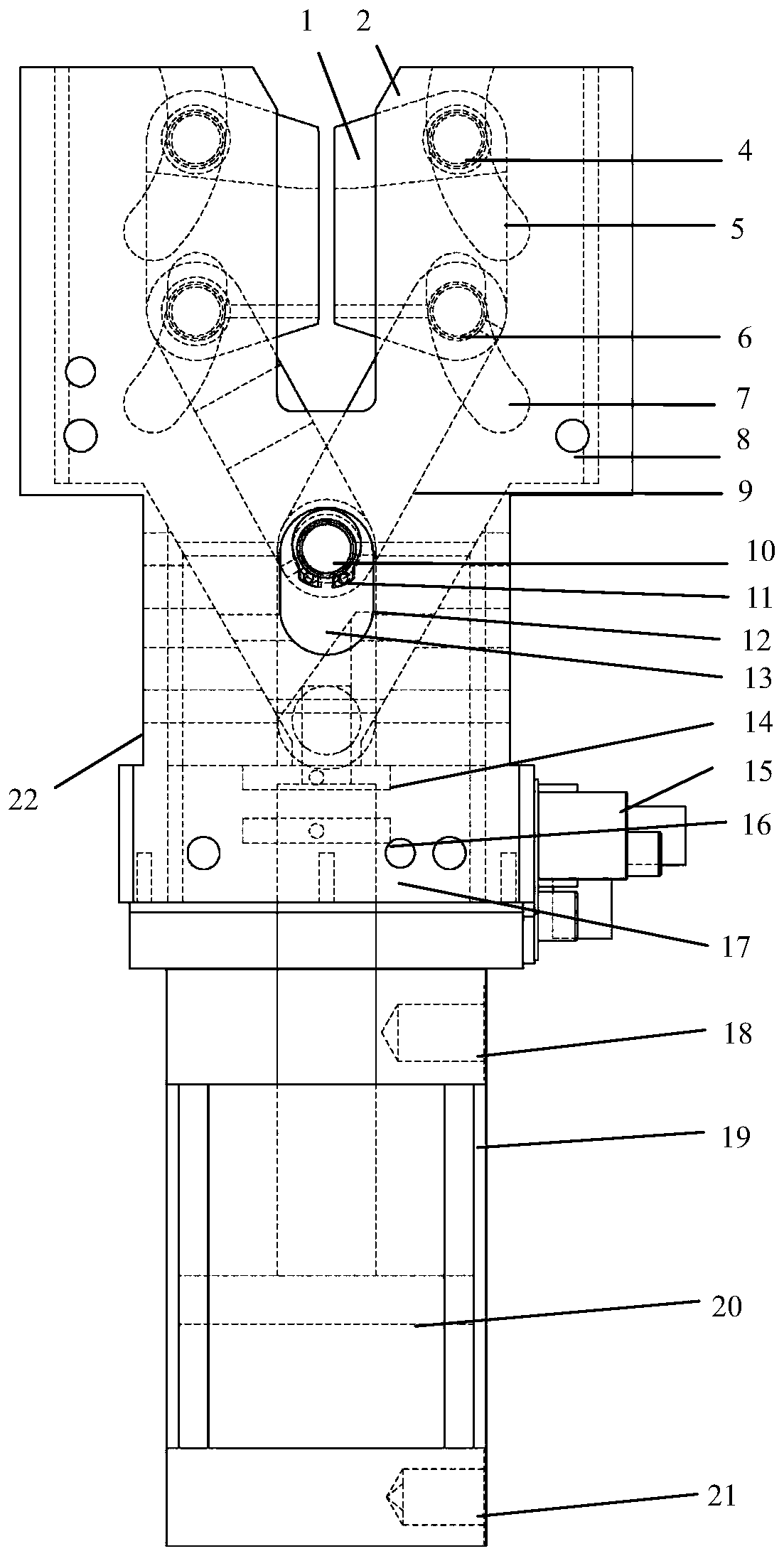
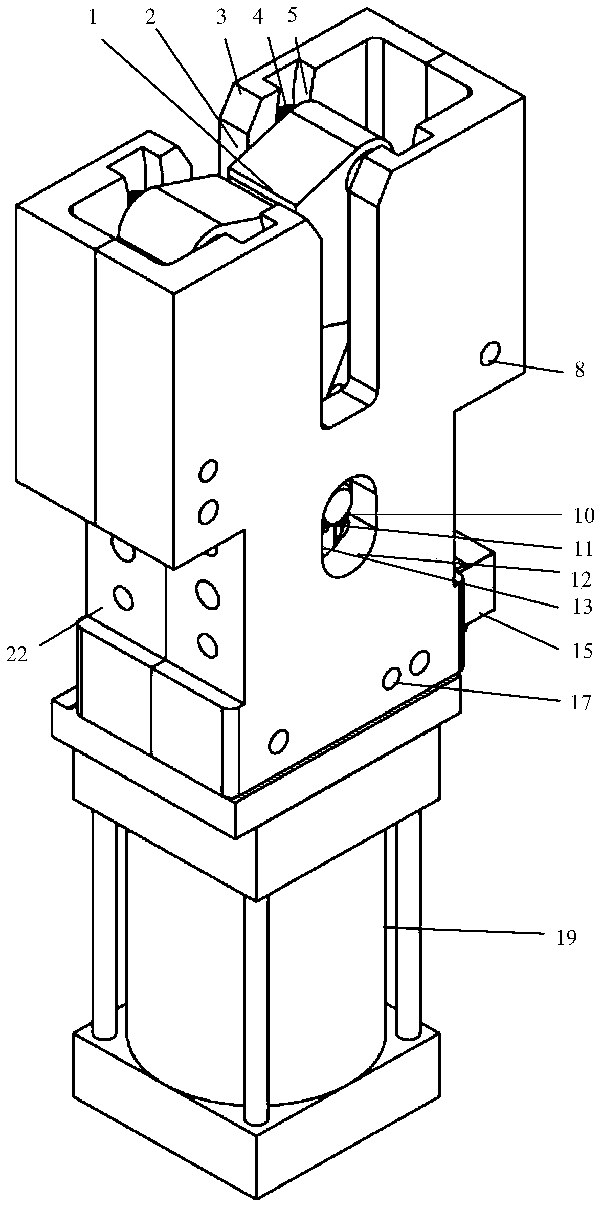
[0025] like Figure 1 ~ Figure 3 As shown, this embodiment provides a chute-type robotic gripper for shearing plates, including a housing 100, a chute-type clamping module 200, a position sensing module 300 and a driving module 400, and the housing 100 is provided with interconnected The chute-type clamping module 200 and the position sensing module 300 are connected to the driving module 400 at the lower end of the casing 100 .

[0026] The upper end of the housing 100 is a symmetrical clamping structure, and is provided with an arc-shaped chute and a middle chute 12. The arc-shaped...


PUM


Abstract

The invention relates to a plate shearing sliding groove type robot gripper. The gripper comprises a shell, a sliding groove type clamping module, a position induction module and a driving module. Thesliding groove type clamping module and the position induction module are arranged in the shell. The lower end of the shell is connected with the driving module. The upper end of the shell is of a symmetrical clamping structure and is provided with arc-shaped sliding grooves and a middle sliding groove. The sliding groove type clamping module is connected with the shell through the sliding grooves. Compared with the prior art, the sliding groove type clamping module adopts the clamping structure comprising a sliding block, connecting rods and the sliding grooves; a cylinder drives the connecting rods through the sliding block to enable clamping fingers to move along the sliding grooves of the shell to implement clamping or loosening. The plate shearing sliding groove type robot gripper has the characteristics of having the automatic centering and positioning, power-enhanced clamping, parallel clamping, parallel loosening, bi-directional symmetrical clamping capabilities, is particularly suitable for the working conditions that an industrial robot grabs plates and the like and meets the requirements for flexible plate shearing production of the robot.

Description

technical field [0001] The invention relates to an industrial vision robot gripper, in particular to a chute type robot gripper for shearing plates. Background technique [0002] At present, the sheet metal grasping methods used in the shearing operation mainly include vacuum suction cups, electromagnetic suction cups, and vacuum and electromagnetic composite suction cups. Although the electromagnetic chuck has a large suction force, it is heavy and expensive. Vacuum suction cups are lightweight, relatively cheap, and widely used. Vacuum and electromagnetic composite suction cups are complex in structure, need to be customized, heavy in weight and high in price. With the development of flexible shearing operations, robotic flexible shearing is also on the agenda. [0003] The sheet metal grasping and clamping devices used in the traditional shearing processing industry generally have the following defects: 1. There is no connecting rod mechanism inside the ordinary cylind...

Claims


Application Information

Patent Timeline
Patent Type & Authority Patents(China)
IPC IPC(8): B23D33/02B23D15/06B25J15/02
CPCB23D15/06B23D33/02B25J15/02
Inventor 刘方湖
Owner SHANGHAI LEADERSOFT INFORMATION TECH CO LTD
Why Eureka
Try Eureka