
Robot motion trajectory planning system, method and device

A robot movement and trajectory planning technology, applied in manipulators, program-controlled manipulators, manufacturing tools, etc., can solve the problems of high staff requirements and low robot use efficiency, and achieve the effect of reducing technical requirements and shortening teaching time

Inactive Publication Date: 2018-11-13
广州神力机器人科技有限公司
View PDF8 Cites 5 Cited by
  • Summary
  • Abstract
  • Description
  • Claims
  • Application Information

AI Technical Summary

Problems solved by technology

[0005] In order to overcome the deficiencies of the prior art, one of the purposes of the present invention is to provide a robot motion trajectory planning system, which can solve the problems of the prior art that require high staff and low efficiency of robots

Method used


Image

  • Robot motion trajectory planning system, method and device
  • Robot motion trajectory planning system, method and device

Examples


Embodiment Construction

[0028] Below, in conjunction with accompanying drawing and specific embodiment, the present invention is described further:

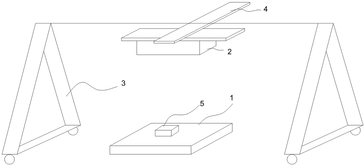
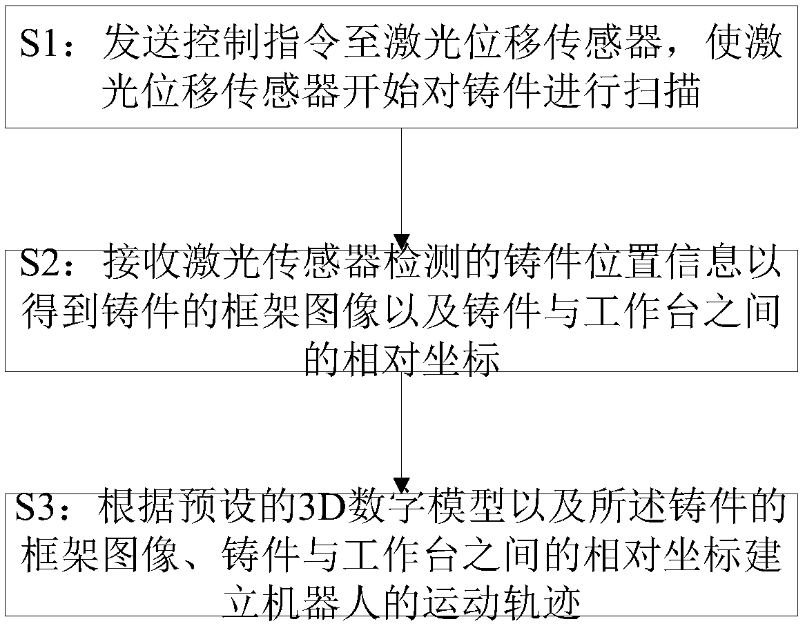
[0029] Such as figure 1 As shown, the present invention discloses a robot trajectory planning system. In order to solve the problems of time-consuming and inaccurate positioning of casting grinding robot trajectory planning, the system includes a workbench 1, a laser displacement sensor 2, a fixed frame 3 and a moving track 4. The moving track 4 is installed on the fixed frame 3, the laser displacement sensor 2 is installed on the moving track 4, the workbench 1 is used to hold the casting 5 to be scanned, the laser displacement sensor 2 is located above the casting 5, and the laser displacement sensor 2 is used to move along the X-axis and Y-axis under the drive of the moving rail 4, so as to scan the casting 5 right above to obtain the frame image of the casting 5.

[0030] In fact, the system of the present invention also includes a host computer, w...


PUM


Abstract

The invention discloses a robot motion trajectory planning system. The system comprises a worktable, a laser displacement sensor, a fixed frame and a movable rail; the movable rail is mounted on the fixed frame; the laser displacement sensor is mounted on the movable rail; the worktable is used for bearing castings to be scanned; and the laser displacement sensor is positioned above the castings,and is used for moving in X-axis and Y-axis directions under driving by the movable rail to scan the castings. The laser displacement sensor scans the whole castings from the upper side, and a motiontrajectory is built according to obtained frame images of the castings, relative coordinates of the castings relative to the worktable and 3D digital models, so that the demonstration time is greatlyshortened, the technical requirements on demonstration staff are greatly reduced, and the precision reaches 0.5-1.0 mm; and the placing positions of the castings have no need to be fixed, so that theeffects of quick clamping and precise positioning can be achieved, the time is saved, and the efficiency is high.

Description

technical field [0001] The invention relates to motion planning technology, in particular to a robot motion track planning system, method and device. Background technique [0002] At present, the trajectory planning of industrial robots on the market is carried out through the teaching pendant. First, the teaching is performed through the teaching pendant, and then the robot moves according to the teaching content, or the robot is first guided through the teaching pendant, and finally the robot is reproduced. Previous teaching content. [0003] This trajectory planning method has the following disadvantages: [0004] 1. The teaching process is cumbersome and time-consuming. If the production process changes, the above teaching procedures must be repeated, and the use efficiency of the robot is low; 2. Professionally trained engineers are required to perform teaching programming, and the technical requirements for operators High, high labor costs. Contents of the inventio...

Claims


Application Information

Patent Timeline
Patent Type & Authority Applications(China)
IPC IPC(8): B25J9/16B25J9/22
Inventor 顾建新
Owner 广州神力机器人科技有限公司
Learn More