Joint structure of modular mechanical arm

A technology of joint structure and manipulator, applied in the field of manipulator, can solve the problems of difficult calculation of manipulator rotation plan, unresponsiveness, few plans, etc., and achieve the effect of convenient expansion and connection, convenient interface and less electrical connection cables

Inactive Publication Date: 2018-11-13
广州市蚺灵科技有限公司
View PDF13 Cites 4 Cited by
  • Summary
  • Abstract
  • Description
  • Claims
  • Application Information

AI Technical Summary

Problems solved by technology

Although the technical scheme disclosed in the application has high structural operation accuracy and strong flexibility, the technical scheme also has some defects. Once a problem occurs, it must be disassembled as a whole when performing maintenance, which is extremely inconvenient
[0005] Simultaneously, the mechanical arms of the above-mentioned two patent disclosure technical solutions all control the joints (steering gear) of each mechanical arm respectively by a control system, and then reach the purpose of moving, and there is only one joint (steering gear) between the mechanical arms. Mechanical connection relationship, in this case, on the one hand, there will be a phenomenon of slow response, on the other hand, when the robot arm is moving, there are fewer calculated solutions, in complex environments, or in the case of obstacles , it is difficult to calculate a more suitable manipulator rotation scheme

Method used


Image

  • Joint structure of modular mechanical arm
  • Joint structure of modular mechanical arm
  • Joint structure of modular mechanical arm

Examples


Embodiment 1

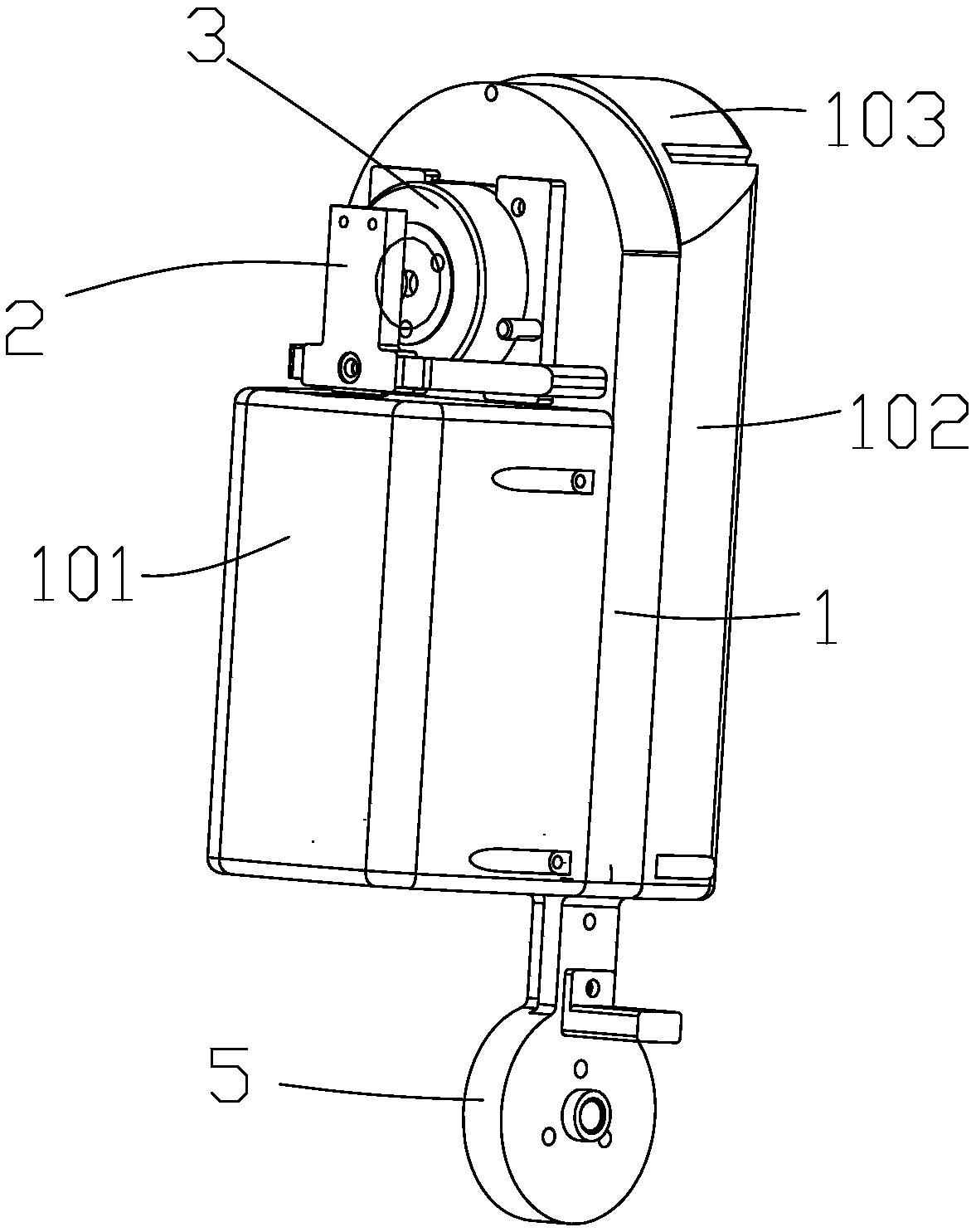
[0066] One of the joint structure implementations of a modular robotic arm of the present invention, such as Figures 1 to 5 As shown, this embodiment provides a joint structure of a modular mechanical arm, including a support frame 1, the support frame is placed longitudinally, and the upper end surface of the support frame 1 is formed as an arched connection area 11, the support The lower end surface of the framework 1 is formed as a rectangular fixing area 12, and the left and right sides of the support framework 1 are provided with joint shells respectively, and the joint shells cover the support framework 1 in a semi-closed manner, and the joint shells include a left shell 101 and the right shell 102, the left shell cavity between the left shell 101 and the support frame 1 is formed as the driving side 14 of the support frame, and the right shell cavity between the right shell 102 and the support frame 1 is formed as The linkage side 13 of the support frame;

[0067] The...

Embodiment 2

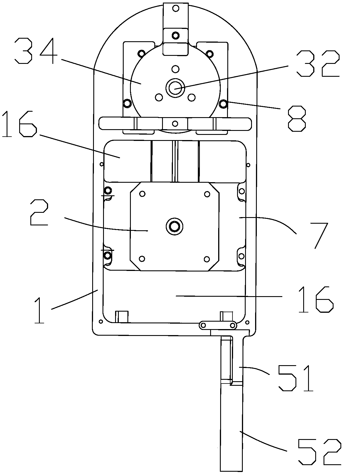
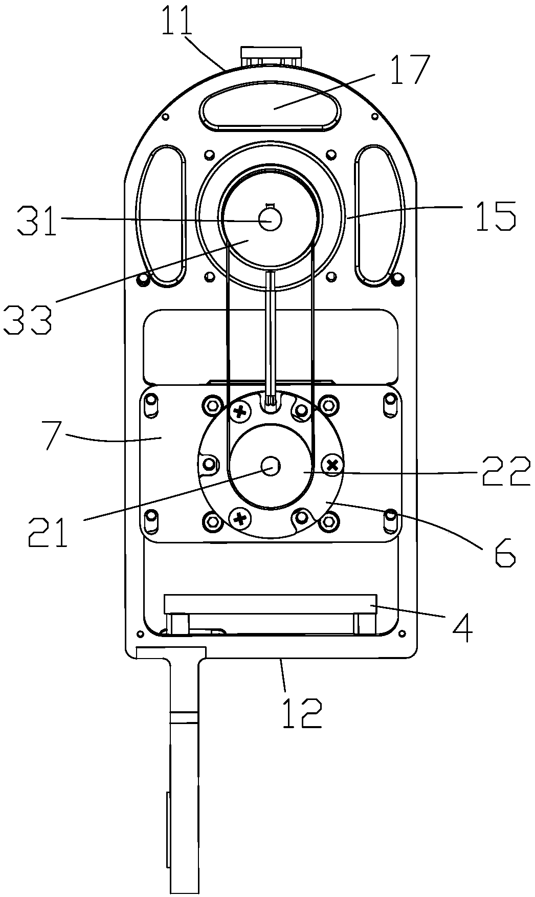
[0080] One of the implementations of the joint structure of a modular robotic arm of the present invention, such as Figures 1 to 5 As shown, the main technical solutions of this embodiment are basically the same as those of Embodiment 1, and the features not explained in this embodiment are explained in Embodiment 1, and will not be repeated here. The difference between this embodiment and Embodiment 1 is that: the supporting frame 1 is provided with a first through hole 15 and a second through hole 16 in sequence from top to bottom, and the first through hole 15 and the second through hole 16 are located on the supporting frame 1 The reducer 3 vertically passes through the first through hole 15 and is fixedly connected with the supporting frame 1 , the reducer input shaft 31 and the reducer output shaft 32 are coaxial and parallel to the driver output shaft 21 .

[0081] The first through hole 15 is a circular hole, and the supporting frame 1 around the first through hole 15...

Embodiment 3

[0085] One of the implementations of the joint structure of a modular robotic arm of the present invention, such as Figures 1 to 5As shown, the main technical solution of this embodiment is basically the same as that of Embodiment 1 or Embodiment 2, and the features not explained in this embodiment are explained in Embodiment 1 or Embodiment 2, and will not be repeated here. . The difference between this embodiment and embodiment 1 or embodiment 2 is that the connector 5 includes a connecting arm 51 and a fixing arm 52, and the upper and lower ends of the connecting arm 51 are fixedly connected to the fixing area 12 and the fixing arm 52, respectively. The fixing arm 52 is formed into a structure consistent with the shape of the mounting plate 34 and is fixedly connected with the mounting plate 34 .

[0086] The vertical distance from the axis center of the output shaft 32 of the reducer to the top of the connection area 11 is greater than the vertical distance from the cent...


PUM


Abstract

The invention provides a joint structure of a modular mechanical arm. The end face of the upper part of a supporting framework of the joint structure is formed as an arch-shaped connection region; theend face of the lower part is formed as a rectangular fixation region; the middle part is provided with a driver; an output shaft, positioned at a linkage side of the supporting framework, of the driver is provided with a driving wheel; the other side, opposite to the driving wheel, of the supporting framework is formed as a driving side; the upper part, close to the connection region, of the supporting framework is provided with a speed reducer; an input shaft, at the same side with the driving wheel, of the speed reducer is provided with a linkage wheel; the speed reducer at the driving side is provided with a speed reducer output shaft; one side, close to the speed reducer output shaft, of the speed reducer is provided with a mounting plate; the driving wheel and the linkage wheel arein transmission connection through a closed belt; the lower part of the supporting framework is provided with a joint integration controller; the joint integration controller is connected with the driver; and the part, close to the edge of one side of the supporting framework, of the fixation region is provided with a connector so as to solve the defects that an existing mechanical arm is not precise in rotation, inconvenient to maintain and tedious and complicated in control.

Description

technical field [0001] The invention relates to the technical field of mechanical arms, in particular to a joint structure of a modular mechanical arm. Background technique [0002] The emergence of robotic arms has helped the modern production process to have more modes of operation. In some special fields, such as the electronics field, robotic arms can achieve more precise installation of electronic components. In some biochemical technology fields, specific In the environment where personnel are not suitable for the detection site, the mechanical arm can help people to realize real-time monitoring of the site, but the mechanical arm in the prior art has many inconveniences. Such as [0003] Chinese patent (publication number "CN107803830A") discloses a seven-degree-of-freedom force feedback hydraulically driven mechanical arm, including a hydraulic control assembly and a connecting rod assembly. The connecting rod assembly includes six first connecting rod assemblies co...

Claims


Application Information

Patent Timeline
Patent Type & Authority Applications(China)
IPC IPC(8): B25J17/00
CPCB25J17/00
Inventor 程龙邴振山刘林林黄凯
Owner 广州市蚺灵科技有限公司
Why Eureka
Try Eureka