Nonmetal frame machine

A non-metal and frame technology, applied in the field of non-metal frame machines, can solve the problems of low efficiency and inability to guarantee accuracy, and achieve the effects of high efficiency, excellent quality and reliable accuracy

Pending Publication Date: 2018-11-13
胡家麟 +1
View PDF0 Cites 0 Cited by
  • Summary
  • Abstract
  • Description
  • Claims
  • Application Information

AI Technical Summary

Problems solved by technology

Mainly solve the technical problems of low efficiency a

Method used


Image

  • Nonmetal frame machine
  • Nonmetal frame machine
  • Nonmetal frame machine

Examples


Example Embodiment

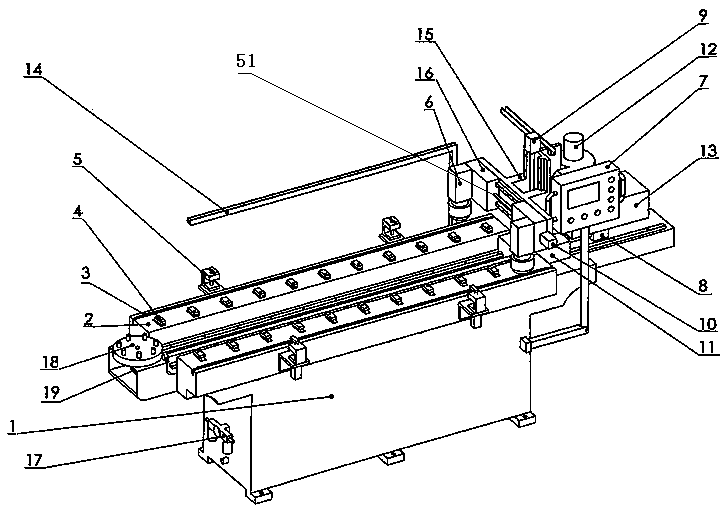
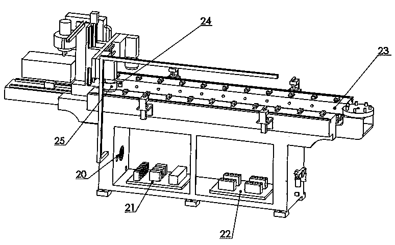
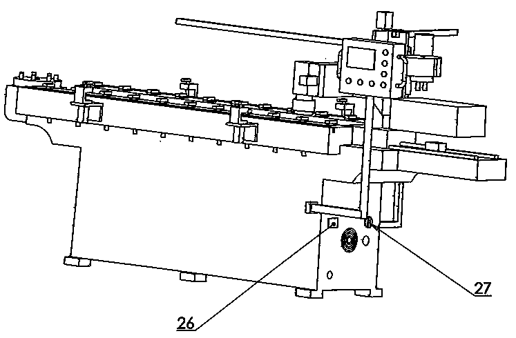
[0020] Example 1, see figure 1 , 2 , 3, 4, 6, 7, and 8, a non-metal frame machine includes a bed 1 and a worktable 2 mounted on the bed. A tool changing turntable 18 is installed at one end of the worktable 2. The tool Replace the turntable 18 with the turntable motor 19 shaft connection, install several sets of pneumatic push rod assemblies 4 symmetrically on the worktable 2, and install multiple sets of rotating presser foot assemblies 5 symmetrically on both sides of the worktable 2. A reference slot 3 and a baffle inserted in the reference slot are provided on both sides. A reference guide rail is provided on the worktable 2, and an X-axis slide table 11 is installed on the reference guide rail. The X-axis slide table 11 is connected to the X-axis motor 8 , The Y-axis guide rail is vertically fixed on the X-axis slide table 11, and a Y-axis slide table 16 is installed at both ends of the Y-axis guide rail. The two Y-axis slide tables 16 are connected to the Y-axis motor 10 t...

Example Embodiment

[0023] Example 2, reference figure 1 , 2 , 3, 5, 6, 7, 8, the pneumatic push rod assembly is replaced by a hydraulic push rod assembly, the hydraulic push rod assembly includes an oil tank 31, the output pipeline of the oil tank is connected to the regulating valve 32, the protection pump 33, and the pumping motor 34 in sequence , Filter 35, pressure regulating valve 36, and then connected to electromagnetic reversing valve 37 and adjustable hydraulic push rod 38. The structure of adjustable hydraulic push rod 38 is similar to that of adjustable pneumatic push rod 30. The fuel tank is provided with a fuel inlet 39 , The liquid level monitor 40, the liquid level gauge 41 and the oil temperature monitor 42, the lower part of the oil tank is provided with a bypass connected to the output pipeline through a safety valve 43, and the upper part of the oil tank is provided with a bypass connected to the output pipeline through an unloading solenoid valve 44. The rest refer to Example 1...


PUM


Abstract

The invention relates to a nonmetal frame machine which is provided for mainly solving the technical problems that an existing processing method is low in efficiency and the precision cannot be ensured. According to the technical scheme, the nonmetal frame machine comprises a machine bed and a workbench mounted on the machine bed. A tool replacement rotary disk connected with a rotary disk motor is mounted at one end of the workbench. A plurality of sets of pneumatic push rod assemblies or hydraulic push rod assemblies are symmetrically mounted on the workbench. Multiple sets of rotary pressure foot assemblies are symmetrically mounted at the ends of the two side edges of the rotary disk motor. Benchmark guide rails are arranged on the workbench. A three-axis processing mechanism is mounted on the benchmark guide rails. A wood dust storage box and a dust collection motor are arranged at the processing end of the workbench. A control cabinet and a gas source solenoid valve control cabinet or a hydraulic valve control cabinet are arranged in the workbench. An operation control box is fixed to the workbench. Proximity switches are arranged in the positions, corresponding to the pneumatic push rod assemblies or the hydraulic push rod assemblies correspondingly. A proximity baffle is arranged on one side of a high-speed cutting motor. The nonmetal frame machine is used for processing frames made of various types of wooden materials and nonmetal materials.

Description

technical field [0001] The invention relates to a machine tool, in particular to a non-metal frame machine used for frame processing of various wooden materials and non-metal materials. Background technique [0002] Timber material frames are used in many occasions, such as mirror frames, picture frames, window frames, door frames and so on. Nowadays, most of the wooden frames are still obtained through semi-artificial and semi-mechanical methods. The desired shape of the wooden frame is obtained by manually pushing the planks against a wood cutter or planer, etc. This method of obtaining the frame by manual feeding is mainly based on the traditional strong pressure hard processing method, which seriously damages the material and damages the quality. Processing can only be done in one direction at most at one time, and processing a piece of wood is not only inefficient, but also the accuracy cannot be guaranteed, especially when processing longer strips of frame materials,...

Claims


Application Information

Patent Timeline
IPC IPC(8): B27C9/02B27G3/00
CPCB27C9/02B27G3/00
Inventor 胡家麟胡安琪
Owner 胡家麟
Why Eureka
Try Eureka