
Brooming device for upper surface of prefabricated laminated slab

A technology of stacking plates and sweeping hair, applied in the direction of manufacturing tools, ceramic molding machines, etc., can solve the problems of low efficiency, difficult to guarantee quality, and high cost of chemical treatment methods, and achieve the goal of improving work efficiency, strong adaptability, and achieving continuity. Effect

Active Publication Date: 2018-11-13
重庆建工高新建材有限公司 +2
View PDF2 Cites 2 Cited by
  • Summary
  • Abstract
  • Description
  • Claims
  • Application Information

AI Technical Summary

Problems solved by technology

The roughening of the joint surface has a great influence on the mechanical performance, but due to the uneven tools and techniques used by component factories (such as brooms, steel brushes, etc. used by prefabricated component factories), not only the efficiency is low, but the quality is also difficult. Guaranteed, the cost of chemical treatment is relatively high. At the same time, brooms and steel brushes are mostly handle-type, which is inconvenient to operate for large components.

Method used


Image

  • Brooming device for upper surface of prefabricated laminated slab
  • Brooming device for upper surface of prefabricated laminated slab
  • Brooming device for upper surface of prefabricated laminated slab

Examples


Embodiment 1

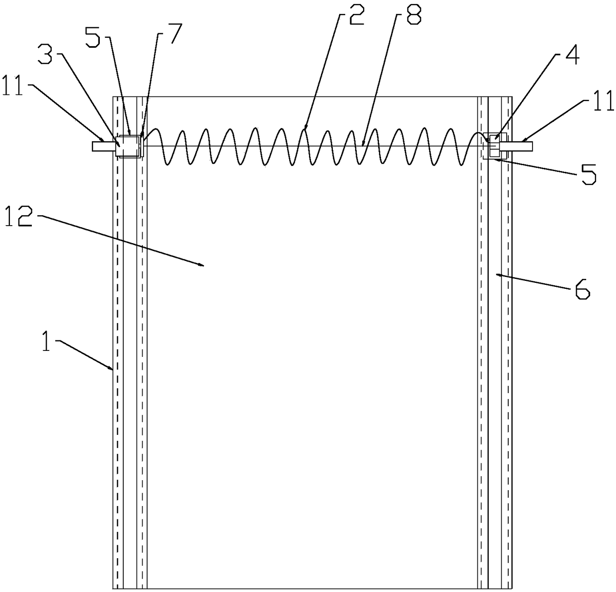
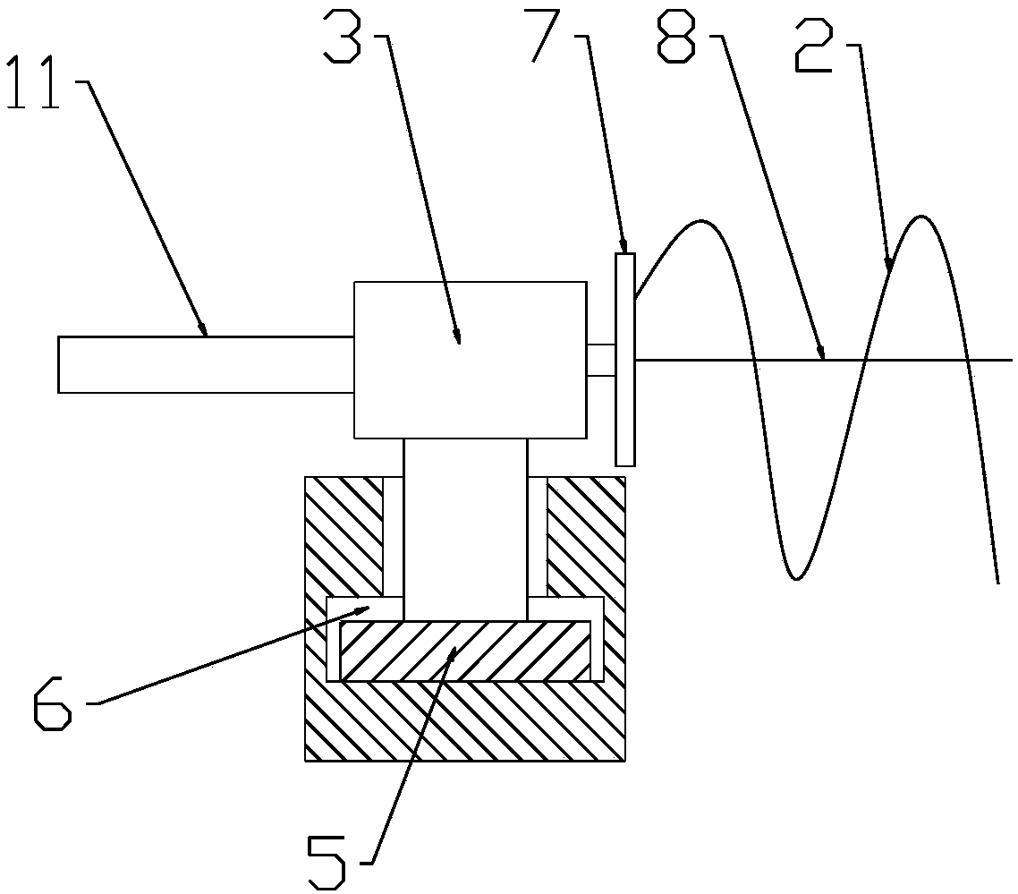
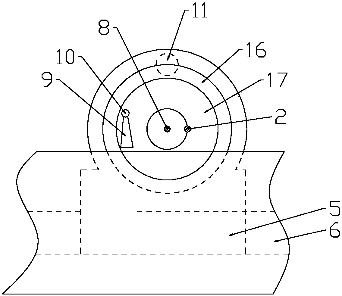
[0025] Such as Figure 1 to Figure 4 As shown, a device for sweeping the surface of a prefabricated laminated board includes a walking track 1 and a sweeping assembly. There is a chute 6, the groove of the running track is parallel to the surface of the prefabricated laminated board 12, and the brushing assembly includes a tension spring 2 located between the running rails 1, and the tension spring 2 is in contact with the surface of the prefabricated laminated board 12, and the two walking A traveling device that can walk along the chute 6 is respectively provided on the track 1. The main driving device and the driven device are respectively installed on the two traveling devices. The two ends of the extension spring 2 are respectively connected with the main driving device and the driven device. The driving device includes a motor 3, the driven device includes a bearing one 4, and the running device on the two running rails 1 is respectively a slider 5 fixed on the lower par...

Embodiment 2

[0030] Such as Figure 5 , Image 6 As shown, a prefabricated laminated board surface sweeping device, wherein, including a walking track 1 and a sweeping assembly, the walking track 1 is two, and the sweeping assembly includes a tension spring 2 between the walking tracks 1, and the walking track 1 A walking device that can walk along the walking track 1 is respectively arranged on the top, and a driving device that drives the extension spring 2 to rotate is installed on the walking device, and the two ends of the extension spring 2 are respectively connected with the corresponding driving device.

[0031] Driving device comprises bearing two 13, and traveling device comprises the roller 14 that is sleeved on the bearing two 13, and roller 14 is positioned at the chute 6 that establishes on the walking track 1, and the outer ring of roller 14 and bearing two 13 is rotationally connected, and extension spring The two ends of 2 are respectively fixedly connected with the outer r...


PUM


Abstract

The invention belongs to the technical field of concrete prefabricated laminated slab production equipment, and particularly relates to a brooming device for the upper surface of prefabricated laminated slab. The brooming device comprises two travelling rails and a brooming assembly, wherein the brooming assembly comprises a tension spring positioned between the travelling rails; travelling devices capable of travelling along the travelling rails are separately arranged on the travelling rails; and drive devices for driving the tension spring to rotate are mounted on the travelling devices; and the two ends of the tension spring are separately connected with the corresponding drive devices. According to the technical scheme adopted by the invention, the brooming device for the upper surface of the prefabricated laminated slab has the characteristics of being simple in structure and convenient to operate, and can be suitable for brooming requirements of prefabricated laminated slab of different dimensions.

Description

technical field [0001] The invention belongs to the technical field of production equipment for concrete prefabricated slabs, and in particular relates to a device for sweeping the surface of prefabricated laminated slabs. Background technique [0002] Composite slab is a better structural form combining prefabrication and cast-in-place concrete. The prefabricated thin slabs (thickness 5-8cm) are combined with the upper cast-in-place concrete layer as a whole and work together. The thin slab is used as the bottom form of the cast-in-place concrete layer, and it is not necessary to support the formwork for the cast-in-place layer; the bottom surface of the thin slab is smooth and flat, and the ceiling can no longer be plastered after the slab joints are treated. This kind of laminated floor slab has the advantages of integrity of cast-in-place floor slab, high rigidity, good crack resistance, no increase in steel consumption, and saving formwork. The construction stage is h...

Claims


Application Information

Patent Timeline
Patent Type & Authority Applications(China)
IPC IPC(8): B28B11/08
CPCB28B11/0818
Inventor 杨再富兰国权石从黎陈敬赵海
Owner 重庆建工高新建材有限公司
Learn More