Mold of electronic equipment shell

A technology for electronic equipment and shells, applied in the field of mold manufacturing, can solve the problems of slow shell mold release, low production efficiency, low degree of automation, etc., and achieve the effects of fast mold release speed, improved production efficiency, and high degree of automation

Inactive Publication Date: 2018-11-13
FUYANG FUBAO INSTR MACHINE TOOL FACTORY
View PDF3 Cites 2 Cited by
  • Summary
  • Abstract
  • Description
  • Claims
  • Application Information

AI Technical Summary

Problems solved by technology

[0004] Aiming at the deficiencies of the prior art, the present invention provides a mold for an electronic device casing, which solves the problems of low automation, slow casing mold release, and low production efficiency

Method used


Image

  • Mold of electronic equipment shell
  • Mold of electronic equipment shell
  • Mold of electronic equipment shell

Examples


Embodiment Construction

[0023] The following will clearly and completely describe the technical solutions in the embodiments of the present invention with reference to the accompanying drawings in the embodiments of the present invention. Obviously, the described embodiments are only some, not all, embodiments of the present invention. Based on the embodiments of the present invention, all other embodiments obtained by persons of ordinary skill in the art without making creative efforts belong to the protection scope of the present invention.

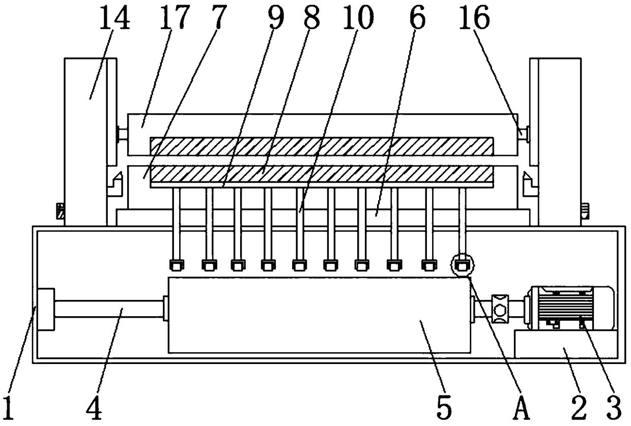
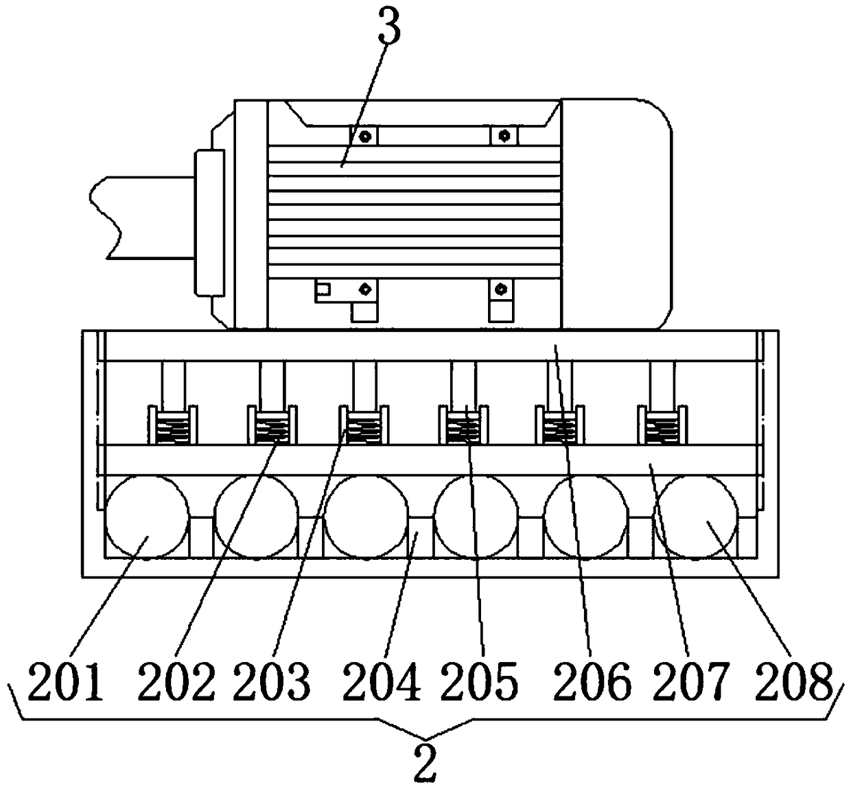
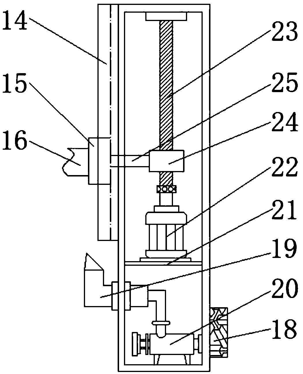
[0024] see Figure 1-5, the present invention provides a technical solution: a mold for an electronic equipment housing, including a base box 1, a shock absorbing device 2 is fixedly connected to the right side of the inner cavity of the base case 1, and the top of the shock absorbing device 2 is fixedly connected to a second A motor 3, the output shaft of the first motor 3 is fixedly connected with a rotating shaft 4 through a coupling, one end of the rotatin...


PUM


Abstract

The invention discloses a mold of an electronic equipment shell. The mold comprises a base box. A damping device is fixedly connected with the right side of an inner cavity of the base box. A first motor is fixedly connected with the top of the damping device. An output shaft of the first motor is fixedly connected with a rotating shaft by a coupler. One end of the rotating shaft is rotatably connected with the left side of the inner cavity of the base box by a bearing. The outer surface of the rotating shaft is fixedly connected with a D-shaped roller. The top of the base box is fixedly connected with a thermal insulation plate. The top of the thermal insulation plate is fixedly connected with a fixed mold. The fixedly mold is internally provided with an fixed mold cavity. The bottom of the fixed mold cavity is in sliding connection with a mold ejecting plate. The invention relates to the technical field of mold manufacturing. According to the mold of the electronic equipment shell, the fixed mold can quickly push out a shaped mold through the mold ejecting plate, depanning speed is high, depanning efficiency is improved, labor is reduced, manual shaped mold taking out is not required, automation is high, and benefits of a factory are increased.

Description

technical field [0001] The invention relates to the technical field of mold manufacturing, in particular to a mold for an electronic equipment casing. Background technique [0002] Under the action of external force, the blank becomes a tool with a specific shape and size. Widely used in punching, die forging, cold heading, extrusion, powder metallurgy parts pressing, die casting, and the forming process of compression molding or injection molding of engineering plastics, rubber, ceramics and other products. The mold has a specific contour or inner cavity Shape, the application of the contour shape with the cutting edge can make the blank separate according to the outline shape, and the application of the inner cavity shape can make the blank obtain the corresponding three-dimensional shape. The mold generally includes two parts, the movable mold and the fixed mold, which can be separated or combined. , take out the parts when they are separated, and inject the blank into t...

Claims


Application Information

Patent Timeline
Patent Type & Authority Applications(China)
IPC IPC(8): B29C45/26B29C45/40B29C45/73F16F15/04F16F15/08
CPCB29C45/26B29C45/4005B29C45/7337F16F15/046F16F15/08
Inventor 谢英骏
Owner FUYANG FUBAO INSTR MACHINE TOOL FACTORY
Why Eureka
Try Eureka