Rear suspension bracket and using method thereof

A technology of rear suspension bracket and combination, applied in the field of auto parts, can solve the problem that the rear suspension bracket cannot meet the durability and other problems, and achieve the effect of generalization, prolonging service life, and easy disassembly and assembly.

Inactive Publication Date: 2018-11-13
ZOTYE INT AUTOMOBILE TRADING CO LTD
View PDF5 Cites 1 Cited by
  • Summary
  • Abstract
  • Description
  • Claims
  • Application Information

AI Technical Summary

Problems solved by technology

[0003] The purpose of the present invention is to provide a rear suspension bracket with simple structure, convenient installation and disassembly, strong versatility, and a reduced risk of cracking at the connection part between the rear suspension and the sub-frame, and a method for using the rear suspension bracket in the prior art. The bracket cannot meet the durability problem under the large load of the powertrain

Method used


Image

  • Rear suspension bracket and using method thereof
  • Rear suspension bracket and using method thereof
  • Rear suspension bracket and using method thereof

Examples


Embodiment Construction

[0031] In the present invention, it should be understood that the terms "length", "width", "upper", "lower", "front", "rear", "left", "right", "vertical", "horizontal" ", "Top", "Bottom", "Inner", "Outer", "Clockwise", "Counterclockwise", "Axial", "Radial", "Circumferential" and other indications are based on The orientation or positional relationship shown in the drawings is only for the convenience of describing the present invention and simplifying the description, and does not indicate or imply that the referred device or element must have a specific orientation, be constructed and operated in a specific orientation, and therefore cannot be understood as Limitations on the Invention.

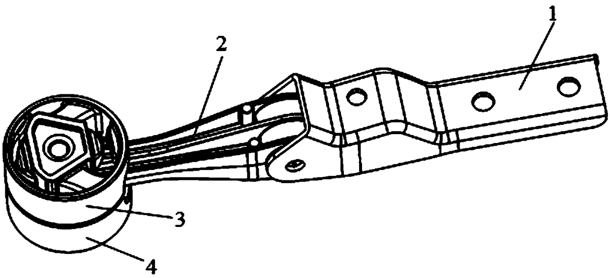
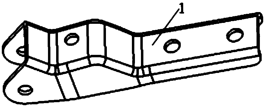
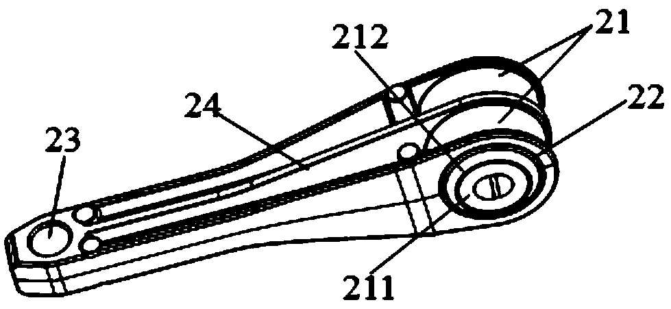
[0032] Such as Figure 1 to Figure 6 As shown, a rear suspension bracket includes bracket II2, bracket I1 connected to the transmission, bush I3 and bush II4 connected to the sub-frame, bush I3 and bush II4 are assembled with interference fit Press-fit into the sub-frame in the same way, t...


PUM


Abstract

The invention discloses a rear suspension bracket, and further discloses a using method of the rear suspension bracket. The rear suspension bracket comprises a bracket II, a bracket I connected with atransmission, a bushing I and a bushing II, wherein the bushing I and the bushing II are connected to an auxiliary vehicle frame. The bushing I and the bushing II are press-mounted in the auxiliary vehicle frame in an interference fit mode after being spliced and assembled. A cavity connected with the bracket II is formed between the bushing I and the bushing II. One end of the bracket II is connected with the bracket I, the other end of the bracket II is inserted into the cavity and connected in a fastened mode through a fastener, and thus a rear suspension system is connected with the auxiliary vehicle frame. The using method of the rear suspension bracket comprises the following steps that 1, the bushing I and the bushing II are spliced and assembled together and press-mounted in the auxiliary vehicle frame; 2, the bushings are press-mounted in mounting holes I in the bracket I, and the bracket I and the bracket II are connected through a fastener; 3, the bracket II is inserted into the cavity formed between the bushing I and the bushing II and connected through the fastener; and 4, the end, away from the bracket II, of the bracket I is connected to the transmission through a fastener.

Description

technical field [0001] The invention belongs to the technical field of auto parts, and in particular relates to a rear suspension bracket and a method for using the rear suspension bracket. Background technique [0002] In the field of automobile manufacturing, the gearbox suspension bracket is one of the key components of the powertrain. Its function is to support the powertrain system and carry the load generated by translation and torque during the powertrain operation. Especially for the three-point mount arrangement, under the limit torque of the engine, the rear point mount of the gearbox needs to bear a large load, so high requirements are put forward for the structural design of the rear point mount. Especially with the application of the cast aluminum sub-frame, it brings great difficulties to the installation of the suspension. If the traditional bolt connection method is still used, under the action of a large load, it is easy to cause the sub-frame to be installe...

Claims


Application Information

Patent Timeline
Patent Type & Authority Applications(China)
IPC IPC(8): B60K17/06
CPCB60K17/06
Inventor 明宇徐作文刘书
Owner ZOTYE INT AUTOMOBILE TRADING CO LTD
Why Eureka
Try Eureka