
Quad-rotor unmanned aerial vehicle with pure belt drive

A four-rotor unmanned aerial vehicle and belt transmission technology, which is applied to rotorcraft, transmission devices to drive multiple propellers, motor vehicles, etc., can solve the problems of increasing the weight of the fuselage transmission system, unsuitable maintenance, and weakened endurance. Achieve the effect of reducing the number of engines and overall body weight, facilitating maintenance and portability, and increasing battery life

Pending Publication Date: 2018-11-13
CHONGQING UNIV
View PDF13 Cites 0 Cited by
  • Summary
  • Abstract
  • Description
  • Claims
  • Application Information

AI Technical Summary

Problems solved by technology

Some existing oil-powered drones use multiple engines to provide power, and each engine drives a rotor. This structure does not require a transmission, but the number of engines makes the failure rate high, which is not suitable for maintenance, and increases the overall weight of the fuselage.
Some inventions use a single engine but use all gears or gears with belt transmission, which increases the weight of the transmission system of the fuselage and weakens its battery life, and a large number of gear transmissions increase its overall cost and poor promotion.
At the same time, the existing long-endurance engines have the disadvantages of being bulky and inconvenient to carry, and the transportation is extremely inconvenient, which limits their application range

Method used


Image

  • Quad-rotor unmanned aerial vehicle with pure belt drive
  • Quad-rotor unmanned aerial vehicle with pure belt drive
  • Quad-rotor unmanned aerial vehicle with pure belt drive

Examples


Embodiment Construction

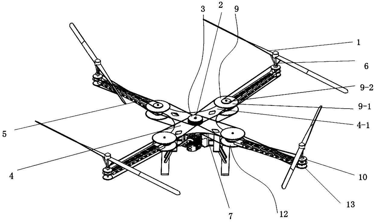
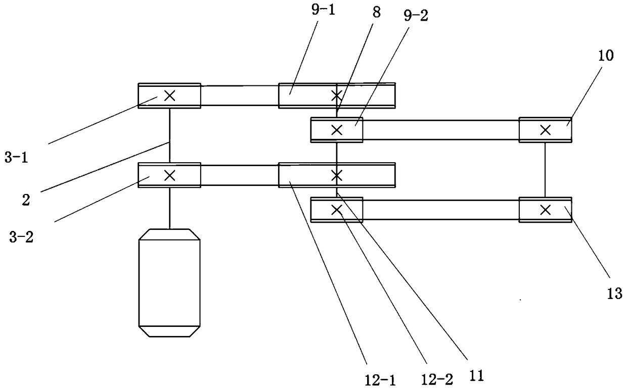
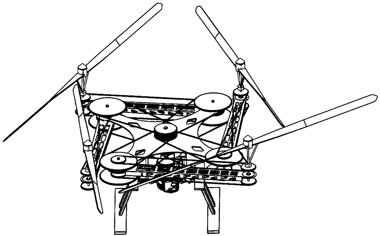
[0016] figure 1 It is a structural schematic diagram of the present invention, figure 2 It is a schematic diagram of the transmission of the single-group pure belt transmission assembly of the present invention, image 3 It is a structural schematic diagram (top view) after folding of the present invention, Figure 4 It is a schematic diagram (bottom view) of the folded structure of the present invention, as shown in the figure: a four-rotor UAV with pure belt transmission in this embodiment includes a body, a driving device arranged on the body, and a four-rotor wheel mounted on the body in rotation. The pure belt transmission system between the rotor 1 and the transmission connection drive device and the rotor 1, the pure belt transmission system includes four groups of pure belt transmission components, and each group of pure belt transmission components is connected to each rotor 1 in a one-to-one corresponding manner. Between the driving device and the rotor 1, the dri...


PUM


Abstract

The invention discloses an oil drive unmanned aerial vehicle with pure belt drive. The oil drive unmanned aerial vehicle with the pure belt drive comprises a vehicle body, a drive device, four rotor wings and a pure belt drive system, wherein the drive device is arranged on the vehicle body, the four rotor wings are rotatably installed on the vehicle body, and the pure belt drive system is connected between the drive device and the rotor wings in a driving mode. The pure belt drive system comprises four groups of pure belt drive assemblies, wherein each group of the pure belt drive assembly and each rotor wing are connected between the drive device and the rotor wings in a one-to-one correspondence and driving mode. The drive device comprises a rotary shaft I, an engine, and a quadruple belt wheel set, wherein the rotary shaft I is rotatably arranged on the vehicle body in the vertical direction, the motor is fixed to the vehicle body and an output shaft of the engine is matched with one end of the rotary shaft I in a driving mode, and the rotary shaft I is fixedly sleeved with the quadruple belt wheel set which is used for driving the four groups of pure belt drive assemblies to operate simultaneously. Through the interaction of all components, not only can the quantity of the engine and the weight of the overall vehicle body be reduced, the cruising ability is increased, thefailure rate is reduced, maintenance and carrying are convenient, but also the manufacturing cost can be reduced, and better popularization performance can be achieved.

Description

technical field [0001] The invention relates to the field of aircraft manufacturing, in particular to a pure belt-driven four-rotor unmanned aerial vehicle. Background technique [0002] In recent years, the quadrotor market has developed rapidly, and various uses of quadrotors have been continuously explored. For example, plant protection and line inspection are now widely used. However, for the long-distance flight requirements, the quadrotors currently relying on electric drive are limited by the battery capacity, which is difficult to achieve. The high energy density and high endurance of traditional fuel engines can guarantee the long-term endurance of quadrotors. Some existing oil-powered drones use multiple engines to provide power, and each engine drives a rotor. This structure does not require a transmission, but the number of engines makes the failure rate high, which is not suitable for maintenance, and increases the overall weight of the fuselage. . Some inven...

Claims


Application Information

Patent Timeline
IPC IPC(8): B64C27/08B64D35/04
CPCB64C27/08B64D35/04
Inventor 宋朝省孙瑞华朱才朝刘思远卫炜
Owner CHONGQING UNIV
Learn More