
Material spiral conveying device

A technology of screw conveying device and conveying device, which is applied in the direction of conveyors, cleaning devices, conveyor objects, etc., and can solve problems such as affecting the normal operation of screw conveying devices, increasing costs, and inconvenient maintenance

Inactive Publication Date: 2018-11-13
泰州市科美伦机电有限公司
View PDF0 Cites 1 Cited by
  • Summary
  • Abstract
  • Description
  • Claims
  • Application Information

AI Technical Summary

Problems solved by technology

The structure design of the existing material screw conveying device is unreasonable. The bearing is arranged inside the screw conveying device. After the material is heated, it enters the screw conveying device through the feeding port. When the temperature exceeds 70°C, the temperature of the bearing will rise, and the oil in the bearing will evaporate, which will easily cause damage, and the bearing will be easily blocked by materials and dust, which will affect the normal operation of the screw conveyor, and the bearing is inside the screw conveyor. , the maintenance is inconvenient, which affects the production progress, and the material consumption is more when replacing the bearing, which greatly increases the cost

Method used


Image

  • Material spiral conveying device

Examples


Embodiment Construction

[0014] The present invention will be described in further detail below in conjunction with the accompanying drawings and specific embodiments.

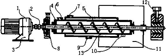
[0015] like figure 1 As shown, a material screw conveying device includes a reducer 1, a coupling 2, a transmission shaft 4, a spiral blade 5, a water-cooled inlet 7, a rolling bearing 8, a water-cooled outlet 9, a trommel 11, a sliding bearing 12 and conveying The device body 13; one end of the reducer 1 is provided with a coupling 2 and connected thereto, the rotating shaft of the reducer 1 is connected with the transmission shaft 4 through the coupling 2, and the front end of the transmission shaft 4 is provided with a rolling bearing 8 And matched with it, the transmission shaft 4 runs through the conveying device body 13 and extends to the outer end of the trommel 11, one end of the conveying device body 13 is arranged in the trommel 11, and the outer end of the trommel 11 is provided with Sliding bearing 12, the sliding bearing...


PUM


Abstract

The invention discloses a material spiral conveying device. A rolling bearing sleeves the front end of a conveying transmission shaft; one end of a conveying device body is arranged in a roller screen; a slide bearing is arranged at the outer end of the roller screen; a rolling bearing and the slide bearing are arranged at two ends of a transmission shaft, and are arranged at the external of the spiral conveying machine body for isolation from materials, so that the temperatures of the bearings are not influenced by the temperature of the materials, the bearings cannot be blocked by the materials and dust, the normal operation of the spiral conveying device is not influenced, the maintenance is convenient, the production progress is not influenced, and the cost is saved; a water cooling inlet is formed in the upper opening end of the conveying device body; a water cooling outlet is formed in the bottom end of the conveying device body; when the device operation is stopped, the materialspiral conveying device is cooled by the water cooling inlet and the water cooling outlet, and the spiral conveying device can be cleaned; one end of the conveying device body is arranged in the roller screen; the materials are screened by adopting the roller screen; the materials are screened to meet requirements; and material particles are nonuniformly removed.

Description

technical field [0001] The invention relates to the technical field of material conveying, in particular to a material screw conveying device. Background technique [0002] Screw conveyors can be divided into shaft screw conveyors and shaftless screw conveyors in terms of conveying form, and can be divided into U-shaped screw conveyors and tubular screw conveyors in terms of appearance. The shafted screw conveyor is suitable for non-viscous dry powder materials and small particle materials (such as: cement, fly ash, lime, grain, etc.), while the shaftless screw conveyor is suitable for conveying viscous and easily entangled materials. (Example: sludge, biomass, garbage, etc.) The working principle of the screw conveyor is that the rotating screw blades push the material to be transported by the screw conveyor, and the force that prevents the material from rotating with the screw conveyor blade is the material's own weight and The frictional resistance of the screw conveyor ...

Claims


Application Information

Patent Timeline
Patent Type & Authority Applications(China)
IPC IPC(8): B65G33/32B65G33/24B65G45/22
CPCB65G33/32B65G33/24B65G45/22B65G2201/042
Inventor 施晓进
Owner 泰州市科美伦机电有限公司
Learn More