
Washing machine

A washing machine and rotating tub technology, applied in the field of washing machines, can solve the problems of remaining between the water tub and the rotating tub, breeding bacteria, loud vibration noise of the washing machine, etc., and achieve the effect of not being easy to secondary pollution, strong stability, and large capacity

Active Publication Date: 2018-11-13
WUXI LITTLE SWAN ELECTRIC CO LTD
View PDF8 Cites 1 Cited by
  • Summary
  • Abstract
  • Description
  • Claims
  • Application Information

AI Technical Summary

Problems solved by technology

[0002] With the continuous development of washing machine technology, washing machines have become more and more large-capacity, and when the washing machine gradually tends to large capacity, it will inevitably lead to the increase of the overall size of the washing machine, so it is very important to provide a washing machine with a small volume and a large capacity. It is necessary; at the same time, when the existing washing machine is washing, the water is distributed in the rotating bucket and the water tank, that is, water is distributed between the water tank and the rotating bucket, and the water consumption is relatively large, resulting in a waste of water resources; The dirt of the washing machine is easy to stay between the bucket and the rotating bucket, which breeds bacteria and because there is water distributed between the bucket and the spinning bucket, the amount of detergent is also large, resulting in waste of detergent resources, which is not conducive to saving costs
[0003] In the existing pulsator washing machine, the water bucket is suspended in the box through the suspension rod shock-absorbing structure. When the eccentricity in the rotating bucket is large, the water bucket is easy to hit the box, and the vibration will be transmitted to the ground through the box during dehydration. , causing the washing machine to vibrate loudly during dehydration
In addition, in the case where the bucket is connected to the upper side of the box body through the suspension rod shock absorbing structure, the vibration is transmitted to the cabinet, requiring the box body to have sufficient strength to support the rotating structure, which increases the difficulty of design and manufacture of the box body

Method used


Image

  • Washing machine
  • Washing machine
  • Washing machine

Examples


Embodiment Construction

[0031] Embodiments of the present invention are described in detail below, examples of which are shown in the drawings, wherein the same or similar reference numerals designate the same or similar elements or elements having the same or similar functions throughout. The embodiments described below by referring to the figures are exemplary and are intended to explain the present invention and should not be construed as limiting the present invention.

[0032] A washing machine 1 according to an embodiment of the present invention will be described below with reference to the accompanying drawings.

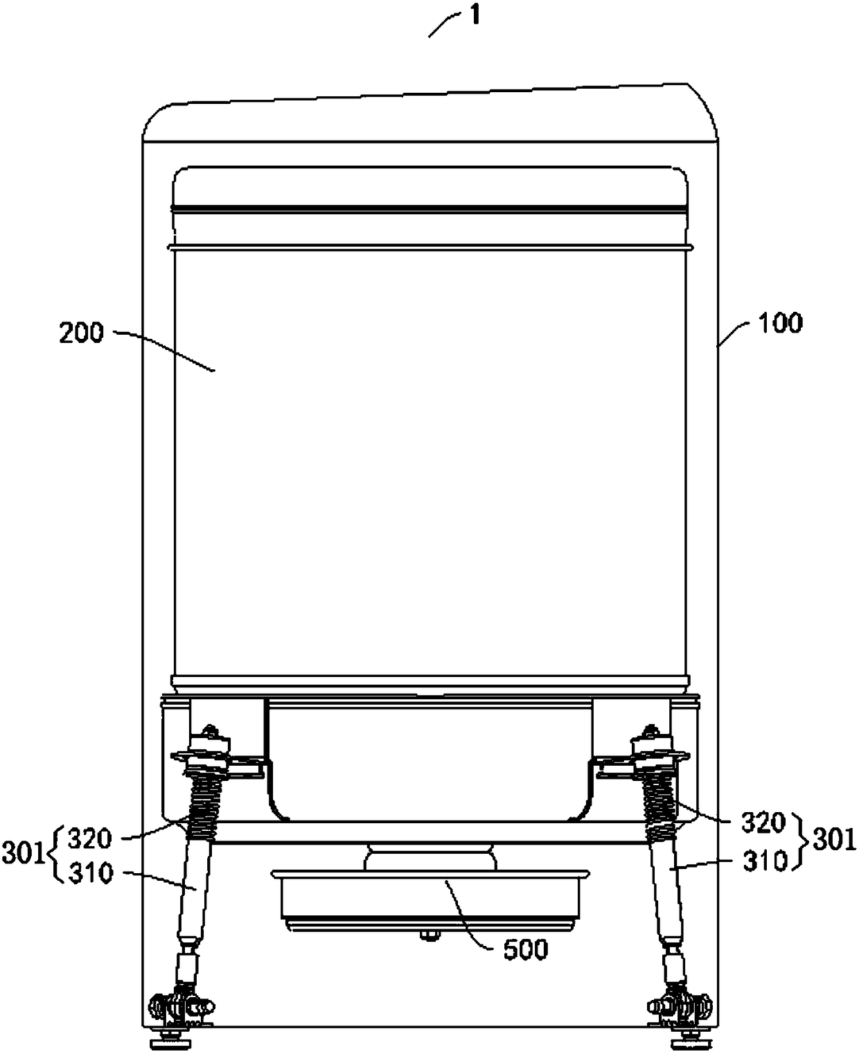
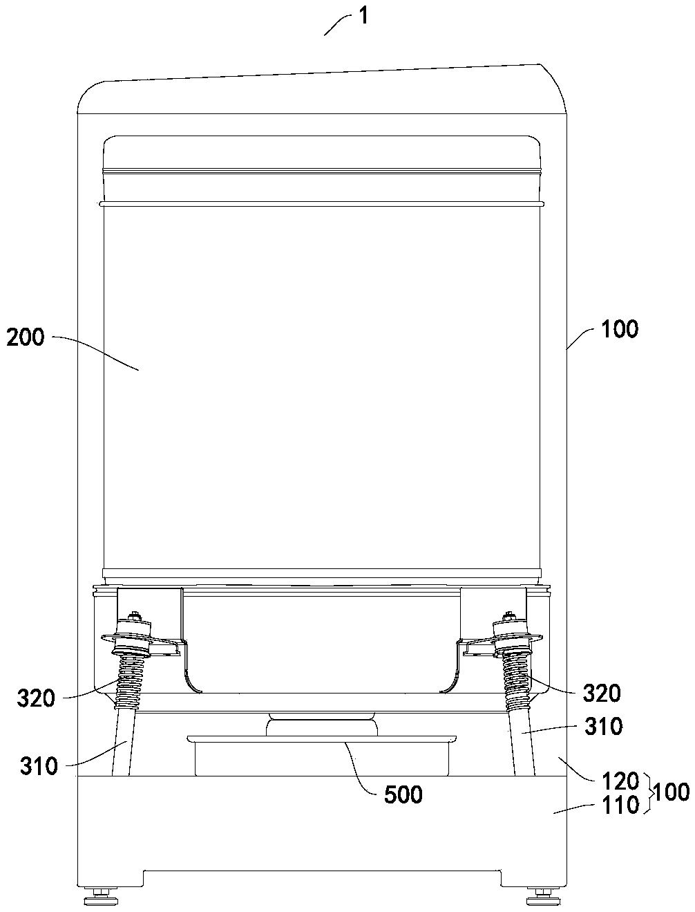
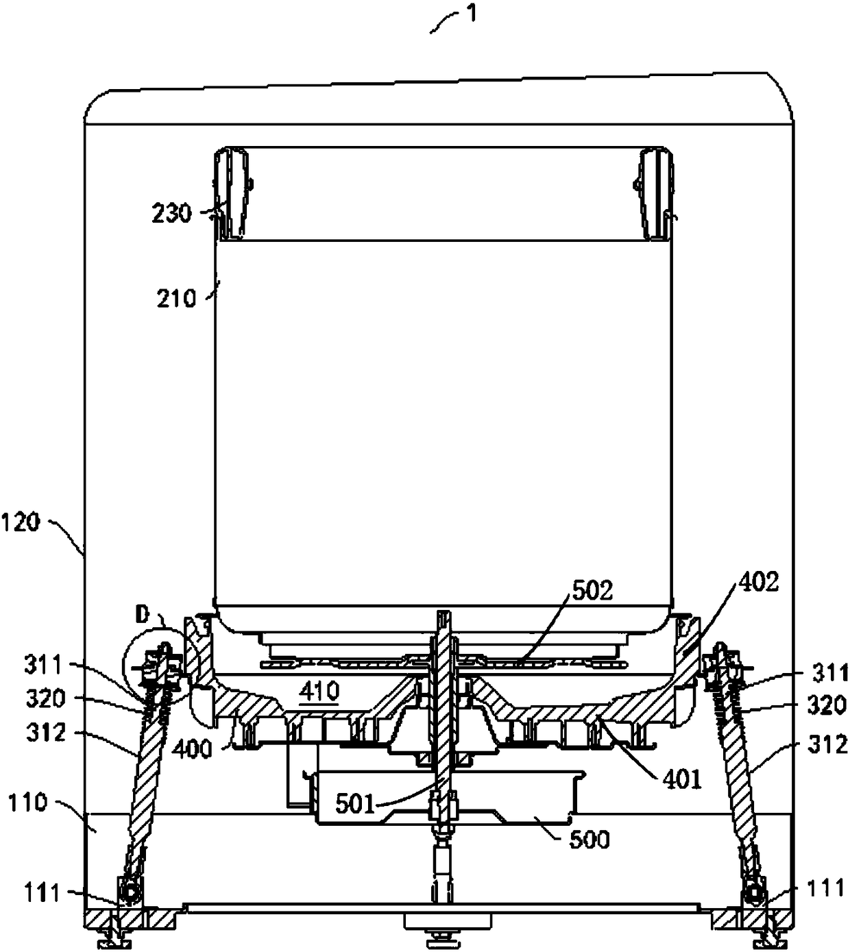
[0033] Such as Figure 1-Figure 6 As shown, the washing machine 1 according to the embodiment of the present invention includes a box body 100 , a rotating tub 200 , a support and damping assembly 300 and a pulsator 600 .

[0034] The rotary tub 200 is rotatably provided in the case 100 . One end of the support shock absorbing assembly 300 is connected to the lower part of the box...


PUM


Abstract

The invention discloses a washing machine. The washing machine comprises a box body, a rotary tub, a supporting shock-absorbing assembly and an impeller, wherein the rotary tub can be rotatably arranged in the box body, one end of the shock-absorbing assembly is connected with the lower portion of the box body, the rotary tub is supported by the other end of the supporting shock-absorbing assembly, and the impeller can be rotatably arranged in the rotary tub. The washing machine has the advantages of large capacity, saving water and environmental friendliness, secondary pollution resistance, strong stability, low noise and the like.

Description

technical field [0001] The invention relates to the technical field of electric appliance manufacturing, in particular to a washing machine. Background technique [0002] With the continuous development of washing machine technology, washing machines have become more and more large-capacity, and when the washing machine gradually tends to large capacity, it will inevitably lead to the increase of the overall size of the washing machine, so it is very important to provide a washing machine with a small volume and a large capacity. It is necessary; at the same time, when the existing washing machine is washing, the water is distributed in the rotating bucket and the water tank, that is, water is distributed between the water tank and the rotating bucket, and the water consumption is relatively large, resulting in a waste of water resources; The dirt of the washing machine is easy to stay between the bucket and the rotating bucket, which breeds bacteria and because there is wat...

Claims


Application Information

Patent Timeline
Patent Type & Authority Applications(China)
IPC IPC(8): D06F37/24D06F39/12D06F37/00D06F39/08
CPCD06F37/24D06F39/083D06F39/12
Inventor 杨伟国史亚成周薇
Owner WUXI LITTLE SWAN ELECTRIC CO LTD
Learn More