Viscous shear type damper

A technology of shear type and damper, which is applied in bridge parts, bridges, buildings, etc., can solve the problems of limited function and achieve the effects of low cost, high efficiency and wide application range

Active Publication Date: 2018-11-13
ZHUZHOU TIMES NEW MATERIALS TECH
View PDF7 Cites 2 Cited by
  • Summary
  • Abstract
  • Description
  • Claims
  • Application Information

AI Technical Summary

Problems solved by technology

This patent document is to improve the performance of the damper by optimizing the arrangement of the

Method used


Image

  • Viscous shear type damper
  • Viscous shear type damper
  • Viscous shear type damper

Examples


Embodiment Construction

[0024] The present invention will be described below in conjunction with the accompanying drawings.

[0025] Aiming at the application of the viscous shear damper in the field of passive vibration control of large civil engineering buildings (such as bridges), the invention provides a viscous shear damper based on a screw transmission mode.

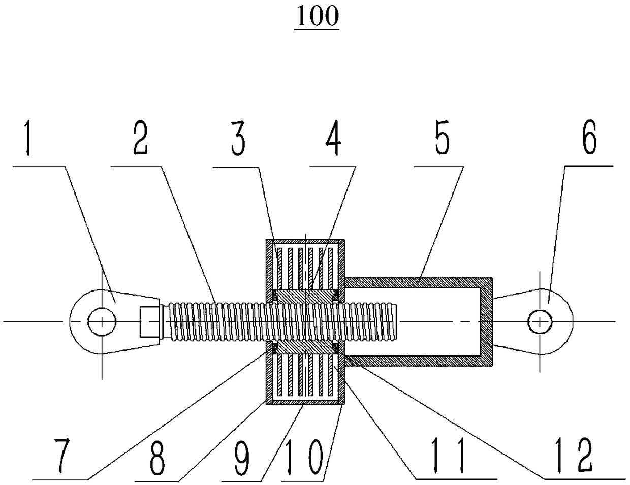
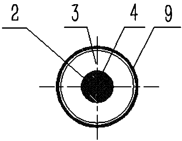
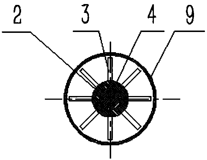
[0026] Such as figure 1 As shown, a viscous shear damper 100 according to the present invention includes a housing 9 . In the illustrated embodiment, the housing 9 is configured as a hollow cylinder, the two ends of which are respectively sealed by a first end cap 8 and a second end cap 10 . However, it is easy to understand that the housing 9 can also be configured as a one-piece cylindrical body with both ends sealed, without a separate end cap for sealing.

[0027] The housing 9 is filled with a shear medium (ie, a viscous fluid) 11 . The shearing medium 11 is well known in the art and can be selected by those skilled in the art acc...


PUM


Abstract

The invention provides a viscous shear type damper comprising a sealed housing, an axial moving part, a rotating moving part and a shearing part. The sealed housing is filled with a shear medium; theaxial moving part axially sealingly passes through the housing; the rotating moving part is arranged in the housing; the axial moving part and the rotating moving part form matching, so that the axialmovement of the axial moving part cam drive the rotating moving part to rotate; and the shearing part is fixedly mounted on the outer periphery of the rotating moving part. The viscous shear type damper has an improved damping force to self weight ratio, and is particularly suitable for the field of bridge vibration resistance.

Description

technical field [0001] The invention relates to a viscous shear damper, in particular to a viscous shear damper used in the anti-vibration field of bridges. Background technique [0002] The viscous shear damper is a damper that uses viscous fluid material and the relative shear motion of the shear plate to generate viscous damping force for the purpose of energy dissipation and vibration reduction. The damping force of the viscous shear damper comes from the resistance of the viscous fluid, which is the viscosity of the viscous fluid. When the damping plate in the viscous fluid moves, it will drive the viscous fluid around it to do shearing motion, and its action will decelerate the faster moving layer of viscous fluid, while the slower moving layer of viscous fluid will accelerate. Therefore, shear stress is generated between the layers of viscous fluid that slide relative to each other. As a result, the kinetic energy of moving objects in the viscous fluid is converted ...

Claims


Application Information

Patent Timeline
IPC IPC(8): E01D19/00
CPCE01D19/00
Inventor 韩鹏飞唐璐宁响亮沈卓刘军庾光忠吴坚
Owner ZHUZHOU TIMES NEW MATERIALS TECH
Why Eureka
Try Eureka