Communication iron tower facilitating replacement of antennas

An antenna and communication technology, which is applied in the field of communication towers that are easy to replace antennas, can solve the problems of difficulty in replacing the antennas of communication towers, reducing the practicality of communication towers, and antenna failures of communication towers, so as to improve convenience, improve anti-theft performance, The effect of improving efficiency

Active Publication Date: 2018-11-13
QINGDAO HUIJINTONG ELECTRIC POWER EQUIP
View PDF6 Cites 6 Cited by
  • Summary
  • Abstract
  • Description
  • Claims
  • Application Information

AI Technical Summary

Problems solved by technology

[0003] After a long period of use in general communication towers, the antennas of the communication towers will fail, which will cause people to need to replace the antennas of the communication towers. Nowadays, the antennas of the communication towers are mostly connected to the communication towers by screws, which leads to the failure of the communication towers. It is more difficult to replace the antenna of the communication tower, which reduces the practicability of the communication tower. Not only that, when the communication tower is in maintenance, people need to climb to the top of the communication tower, so people install a ladder on the communication tower, but the installation of the ladder will also cause problems. Cause some irrelevant personnel to climb up the communication tower, thereby causing damage to the antenna, and even leading to the theft of the antenna

Method used


Image

  • Communication iron tower facilitating replacement of antennas
  • Communication iron tower facilitating replacement of antennas
  • Communication iron tower facilitating replacement of antennas

Examples


Embodiment Construction

[0025] The present invention is described in further detail now in conjunction with accompanying drawing. These drawings are all simplified schematic diagrams, which only illustrate the basic structure of the present invention in a schematic manner, so they only show the configurations related to the present invention.

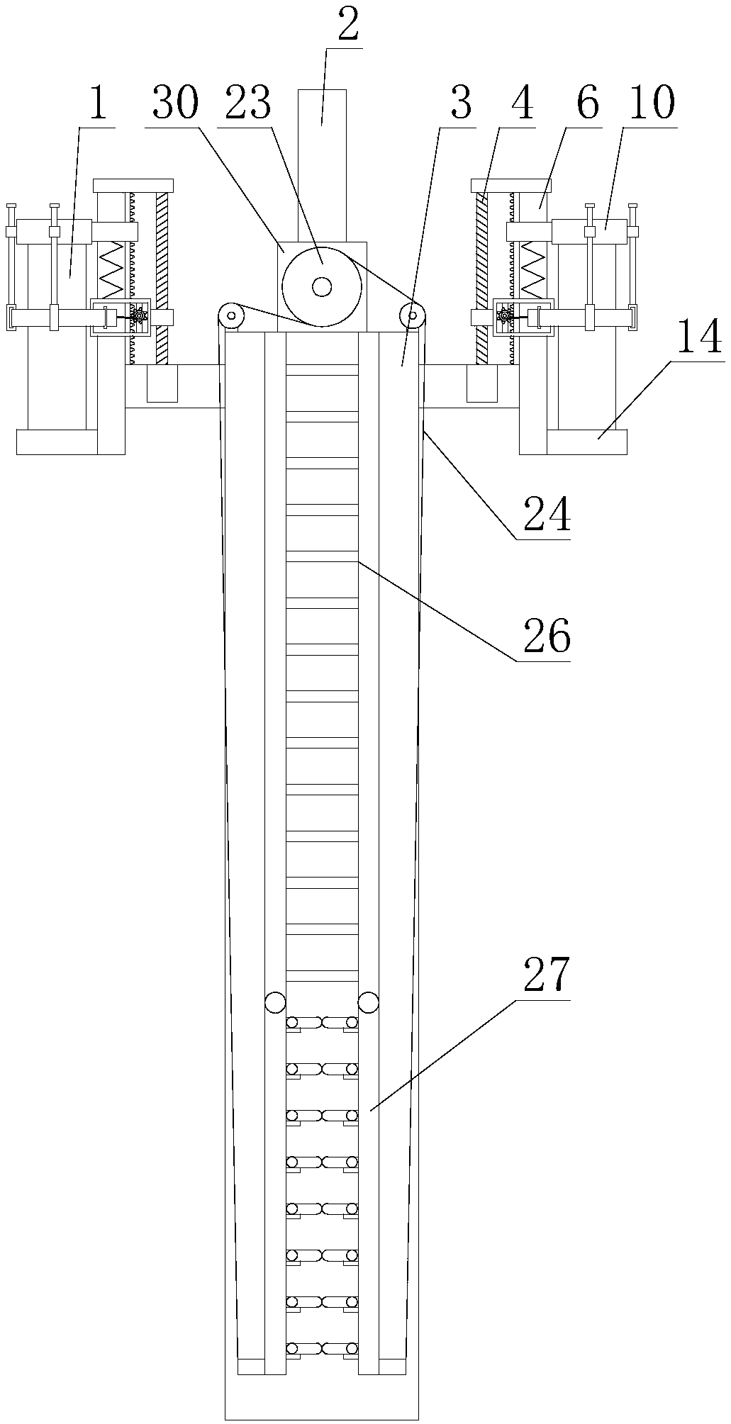
[0026] like figure 1 As shown, a communication tower that is convenient for antenna replacement includes a tower body 3 and at least two antennas 1, and also includes an overhaul mechanism and at least two installation mechanisms. The overhaul mechanism is arranged on one side of the tower body 3, and each installation mechanism The circumferential direction is evenly arranged on the outer circumference of the top of the tower body 3, the number of the installation mechanism is consistent with the number of the antenna 1, and the installation mechanism corresponds to the antenna 1 one by one, and the antenna 1 is arranged on the installation mechanism;

[002...


PUM


Abstract

The invention relates to a communication iron tower facilitating replacement of antennas. The communication iron tower comprises a tower body and the two or more antennas and further comprises an overhaul mechanism and two or more mounting mechanisms. Each mounting mechanism comprises a first driving assembly, a platform, a supporting rod, a bottom base, a top base, a lifting sleeve, a spring, a rack, a reinforcing assembly and two or more supporting assemblies. The overhaul mechanism comprises a second driving assembly, a climbing ladder, two rotating rods, two steel wire ropes, two or more climbing rods and two or more limiting blocks. According to the communication iron tower facilitating replacement of the antennas, through the mounting mechanisms, the convenient degree of antenna disassembly and assembly is increased, thus the efficiency of antenna replacement of workers is improved, and the practicality of the communication iron tower is improved; and through the overhaul mechanism, rotation of the two rotating rods is achieved, thus retracting and extending of climbing rods are achieved, the convenient degree of overhaul of the communication iron tower is increased, meanwhile, the anti-theft performance of the communication iron tower is improved, and thus the practicability of the communication iron tower is further improved.

Description

technical field [0001] The invention relates to the field of communication iron towers, in particular to a communication iron tower that facilitates antenna replacement. Background technique [0002] The communication tower is composed of steel components such as tower body, platform, lightning rod, ladder, antenna support, etc., and has been treated with hot-dip galvanized anticorrosion. It is mainly used for microwave, ultrashort wave, wireless network signal transmission and launch, etc. One, widely used in people's life. [0003] After a long period of use in general communication towers, the antennas of the communication towers will fail, which will cause people to need to replace the antennas of the communication towers. Nowadays, the antennas of the communication towers are mostly connected to the communication towers by screws, which leads to the failure of the communication towers. It is more difficult to replace the antenna of the communication tower, which reduce...

Claims


Application Information

Patent Timeline
Patent Type & Authority Applications(China)
IPC IPC(8): E04H12/18H01Q1/12
CPCE04H12/182H01Q1/12
Inventor 齐进才
Owner QINGDAO HUIJINTONG ELECTRIC POWER EQUIP
Why Eureka
Try Eureka