Timing positioning mechanism of overhead camshaft gear

A technology of camshaft gear and positioning mechanism, which is applied to valve devices, mechanical equipment, engine components, etc., can solve problems such as difficult to find, difficult to align, and low efficiency, so as to prevent assembly errors, improve assembly efficiency and assembly quality Effect

Inactive Publication Date: 2018-11-13
GUANGXI YUCHAI MASCH CO LTD
View PDF6 Cites 0 Cited by
  • Summary
  • Abstract
  • Description
  • Claims
  • Application Information

AI Technical Summary

Problems solved by technology

The camshaft cover and other parts can only be assembled after the camshaft is aligned according to the timing, which is inefficient
[0007] In the process of engine maintenance, if the cylinder head needs to be disassembled, the camshaft 4 is generally not disassembled. When the cylinder head is reinstalled, i

Method used


Image

  • Timing positioning mechanism of overhead camshaft gear
  • Timing positioning mechanism of overhead camshaft gear
  • Timing positioning mechanism of overhead camshaft gear

Examples


Embodiment Construction

[0020] The specific embodiments of the present invention will be described in detail below in conjunction with the accompanying drawings, but it should be understood that the protection scope of the present invention is not limited by the specific embodiments.

[0021] Unless expressly stated otherwise, throughout the specification and claims, the term "comprise" or variations thereof such as "includes" or "includes" and the like will be understood to include the stated elements or constituents, and not Other elements or other components are not excluded.

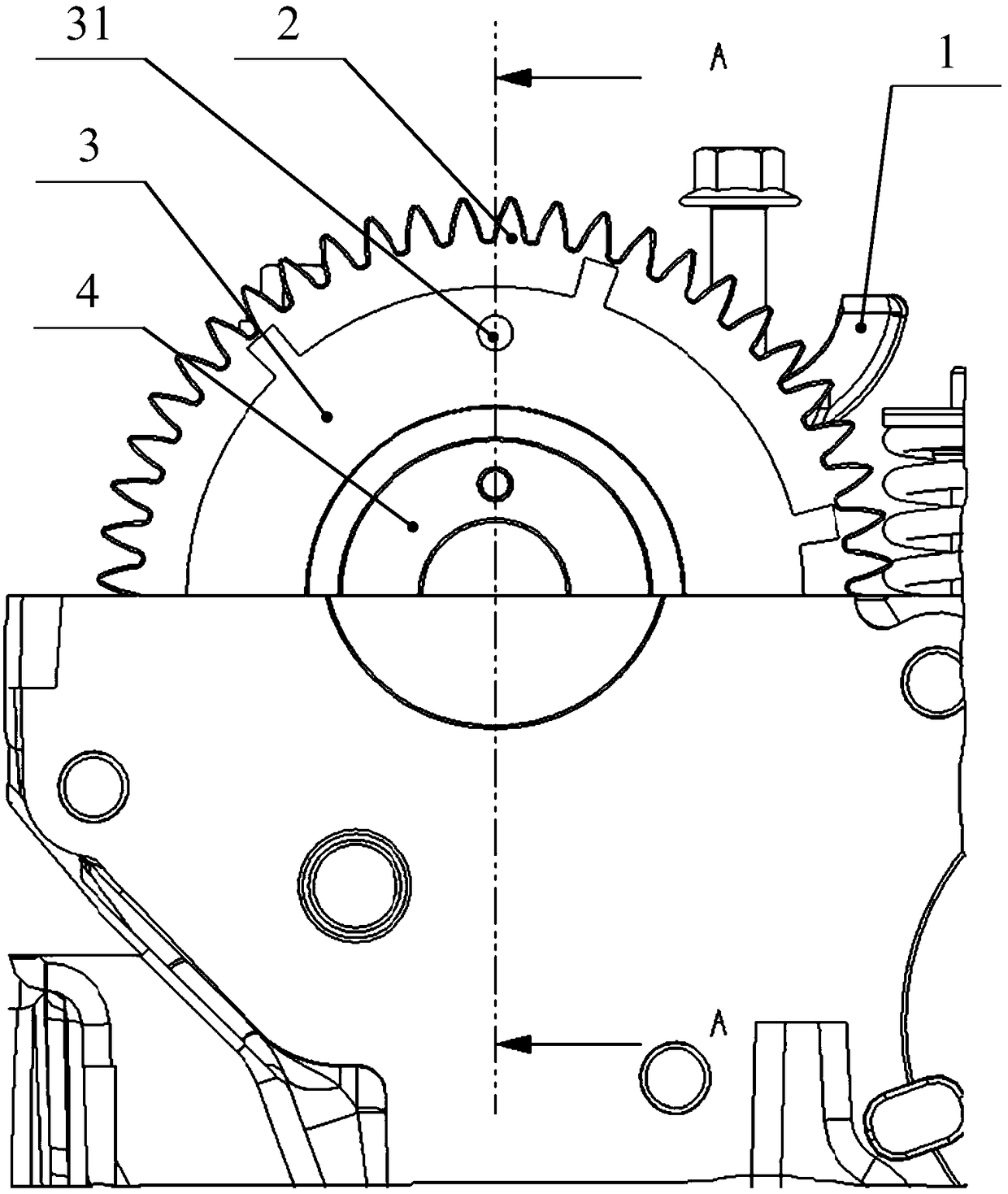
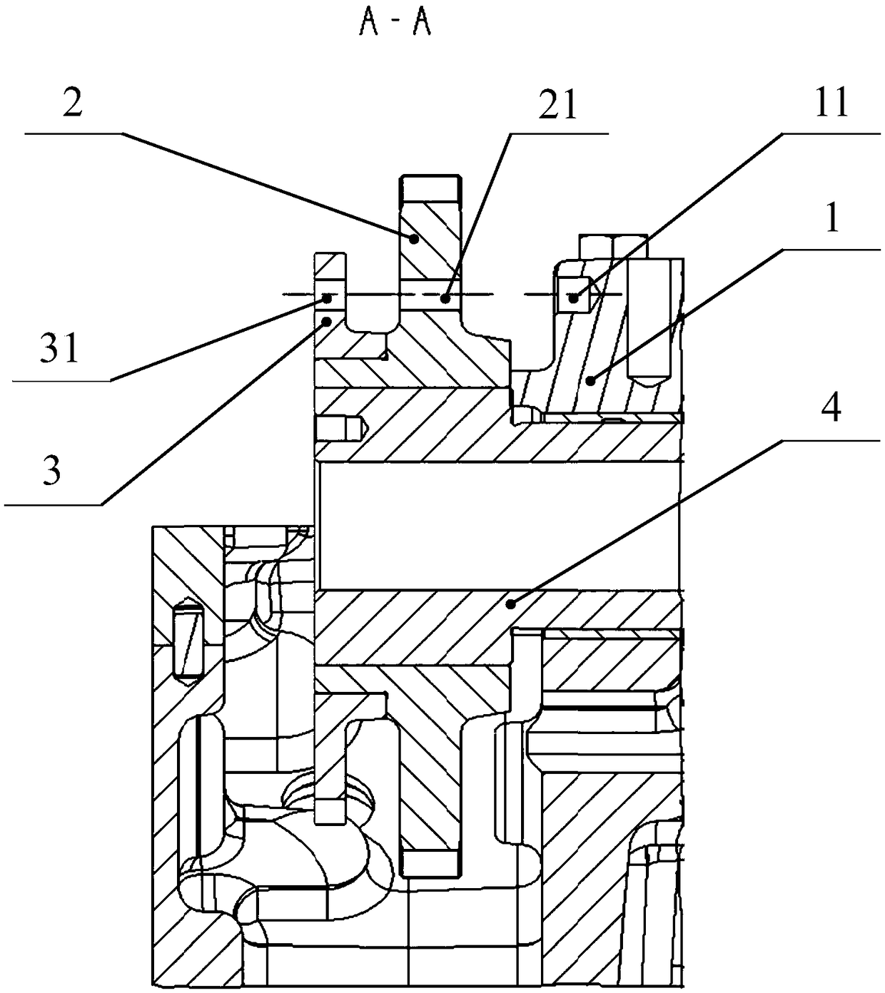
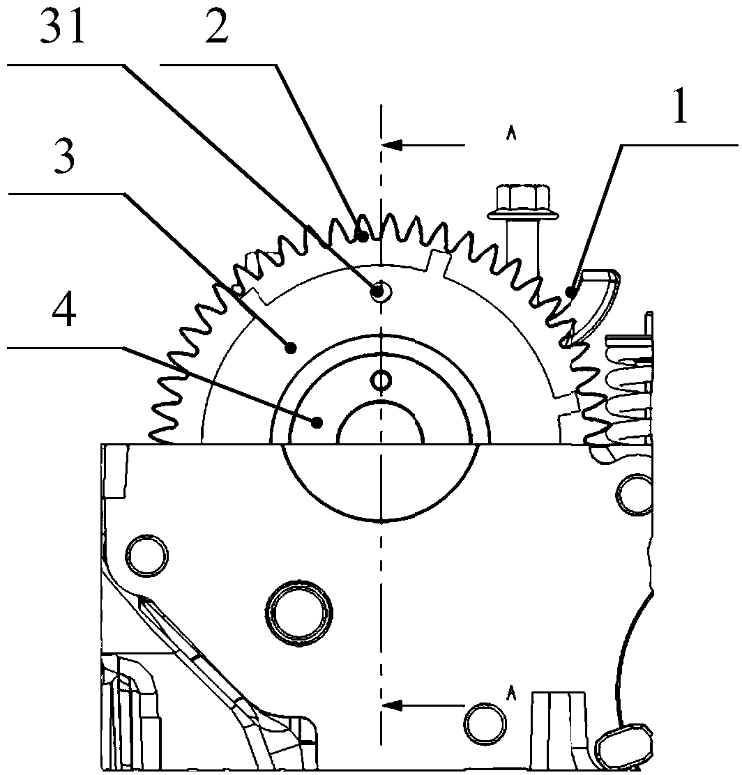
[0022] Such as Figure 1 to Figure 2 as shown, figure 1 It is a schematic front view of a timing positioning mechanism according to an embodiment of the present invention. figure 2 It is an A-A sectional schematic diagram of a timing positioning mechanism according to an embodiment of the present invention. A timing positioning mechanism for an overhead camshaft gear according to a preferred embodiment of the present i...


PUM


Abstract

The invention discloses a timing positioning mechanism of an overhead camshaft gear. The timing positioning mechanism comprises a positioning blind hole, a gear positioning through hole, a signal panel positioning through hole and a pin. The positioning blind hole is formed in one face of a camshaft cover. The gear positioning through hole is formed in a gear disc of the camshaft gear. The signalpanel positioning through hole is formed in the panel face of a camshaft signal panel. The pin penetrates through the signal panel positioning through hole and the gear positioning through hole and isfinally inserted into the positioning blind hole, and then the relative positions of the camshaft cover, the camshaft gear and the camshaft signal panel are fixed. According to the timing positioningmechanism of the overhead camshaft gear, a camshaft and the camshaft gear can be fixed to correct relative positions, and assembly errors caused by relative rotation of the camshaft and the camshaftgear are avoided.

Description

technical field [0001] The invention relates to the field of internal combustion engines, in particular to a timing positioning mechanism for overhead camshaft gears. Background technique [0002] There are two types of engine camshafts: mid-mounted and overhead-mounted, and each structure has certain advantages and different disadvantages. High-speed engines generally use overhead camshafts to reduce valve flying due to the inertial force generated by the arrangement of tappets and other parts during high-speed operation. [0003] At present, the assembly of the overhead camshaft gear mainly ensures the correct phase through point-to-point assembly. If the timing point is wrong during the assembly process, it will lead to valve topping failure. [0004] The timing mark on the timing gear on the overhead camshaft in the prior art must be matched with the timing mark on the camshaft idler gear during the assembly process. If Inaccurate alignment will lead to wrong timing of...

Claims


Application Information

Patent Timeline
IPC IPC(8): F01L1/053F01L1/46
CPCF01L1/053F01L1/46
Inventor 向本杰王鹏程覃文黎华文王志刚刘文元
Owner GUANGXI YUCHAI MASCH CO LTD
Why Eureka
Try Eureka