Supercharge Your Innovation With Domain-Expert AI Agents!

High-pressure fuel pump for a fuel injection system

A fuel injection system and high-pressure fuel pump technology, applied in fuel injection pumps, fuel injection devices, charging systems, etc., can solve problems such as piston sticking, achieve increased service life, internal friction optimization, and large rotational movement components Effect

Pending Publication Date: 2018-11-13
CONTINENTAL AUTOMOTIVE GMBH
View PDF6 Cites 0 Cited by
  • Summary
  • Abstract
  • Description
  • Claims
  • Application Information

AI Technical Summary

Problems solved by technology

Thus precisely at this position in the sleeve and also on the pump piston there is increased friction, which leads to increased wear, for example on the coating and on the pump piston itself and can cause the piston to jam.

Method used


Image

  • High-pressure fuel pump for a fuel injection system
  • High-pressure fuel pump for a fuel injection system
  • High-pressure fuel pump for a fuel injection system

Examples


Embodiment Construction

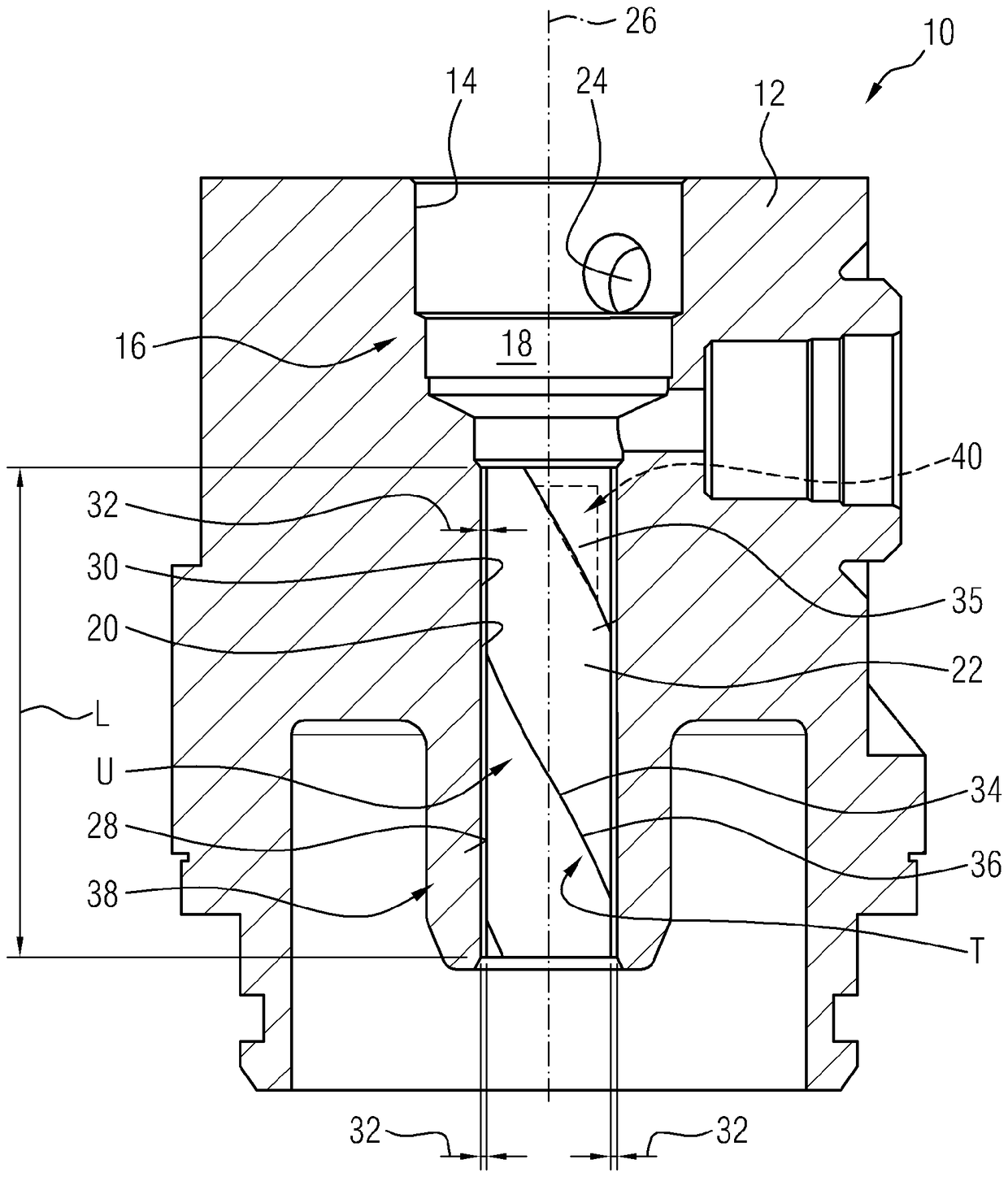
[0032] figure 1 A schematic sectional view of a high-pressure fuel pump 10 is shown, with which high pressure is applied to fuel, in particular gasoline. The high-pressure fuel pump 10 has a housing 12 in which a housing bore 14 is formed, which forms a pressure chamber 18 at an end region 16 . Adjacent to the end region 16 , the housing bore 14 forms a guide bore 20 in which a pump piston 22 is arranged. During operation, fuel is supplied to the pressure chamber 18 via the feed hole 24 . The pump piston 22 moves upwards and downwards along the displacement axis 26 in the guide bore 20 and thus reduces the volume of the pressure chamber 18 . In this way, the fuel located in the pressure chamber 18 is compressed and thus has a high pressure applied thereto.

[0033] In the current embodiment, the guide hole 20 is directly formed in the housing 12 . However, it is also conceivable that an additional sleeve is inserted into the housing bore 14 , in which sleeve the guide bore...


PUM


Abstract

The invention relates to a high-pressure fuel pump (10) having a pump piston (22) and having a piston rotation inducing device (38) which induces a rotation of the pump piston (22) about a movement axis (26), along which the pump piston moves in translational fashion, during the operation of the pump piston (22).

Description

technical field [0001] The invention relates to a high pressure fuel pump for applying high pressure to fuel in a fuel injection system. Background technique [0002] High-pressure fuel pumps in fuel injection systems serve to apply high pressure to the fuel, wherein the pressure lies, for example, in the range from 150 bar to 400 bar in gasoline internal combustion engines and in the range from 1500 bar to 3000 bar in diesel internal combustion engines . The greater the pressure that can be generated in a particular fuel, the lower the emissions induced in the combustion chamber during combustion, which is particularly advantageous in the context of the need to reduce emissions to a greater extent. [0003] Such high-pressure fuel pumps are usually designed as piston pumps, wherein a pump piston is moved in translation along a displacement axis in a housing bore forming a pressure chamber, and the pump piston is compressed by means of the displacement in the pressure chamb...

Claims


Application Information

Patent Timeline
IPC IPC(8): F02M59/02F02M59/44F04B53/14
CPCF02M59/025F02M59/44F04B53/14F02M59/02F02M59/105F02M2200/02F02M59/10F02M55/002
Inventor B.韦利施L.克勒M.毛尔S.迪尔克斯
Owner CONTINENTAL AUTOMOTIVE GMBH
Features
  • R&D
  • Intellectual Property
  • Life Sciences
  • Materials
  • Tech Scout
  • Unparalleled Data Quality
  • Higher Quality Content
  • 60% Fewer Hallucinations
Learn More