Movable and lockable equipment base

A locking and equipment technology, applied in the direction of mechanical equipment, mobile frame, engine frame, etc., can solve the problems of troublesome locking, unreliable locking, small contact area between the universal wheel and the ground, etc., and achieve beautiful appearance, Overcoming the effect of wheel leakage

Pending Publication Date: 2018-11-13
李强
View PDF0 Cites 0 Cited by
  • Summary
  • Abstract
  • Description
  • Claims
  • Application Information

AI Technical Summary

Problems solved by technology

However, on the one hand, the contact area between the universal wheel and the ground is small, and it is not stable enough on smooth indoor surfaces such as marble surfaces and ceramic tiles; You need to find all the universal wheel brake pedals, and then press or step on them one by one
If only one or two of them are locked, the other wheels can move and the locking is not reliable

Method used


Image

  • Movable and lockable equipment base
  • Movable and lockable equipment base
  • Movable and lockable equipment base

Examples


Embodiment

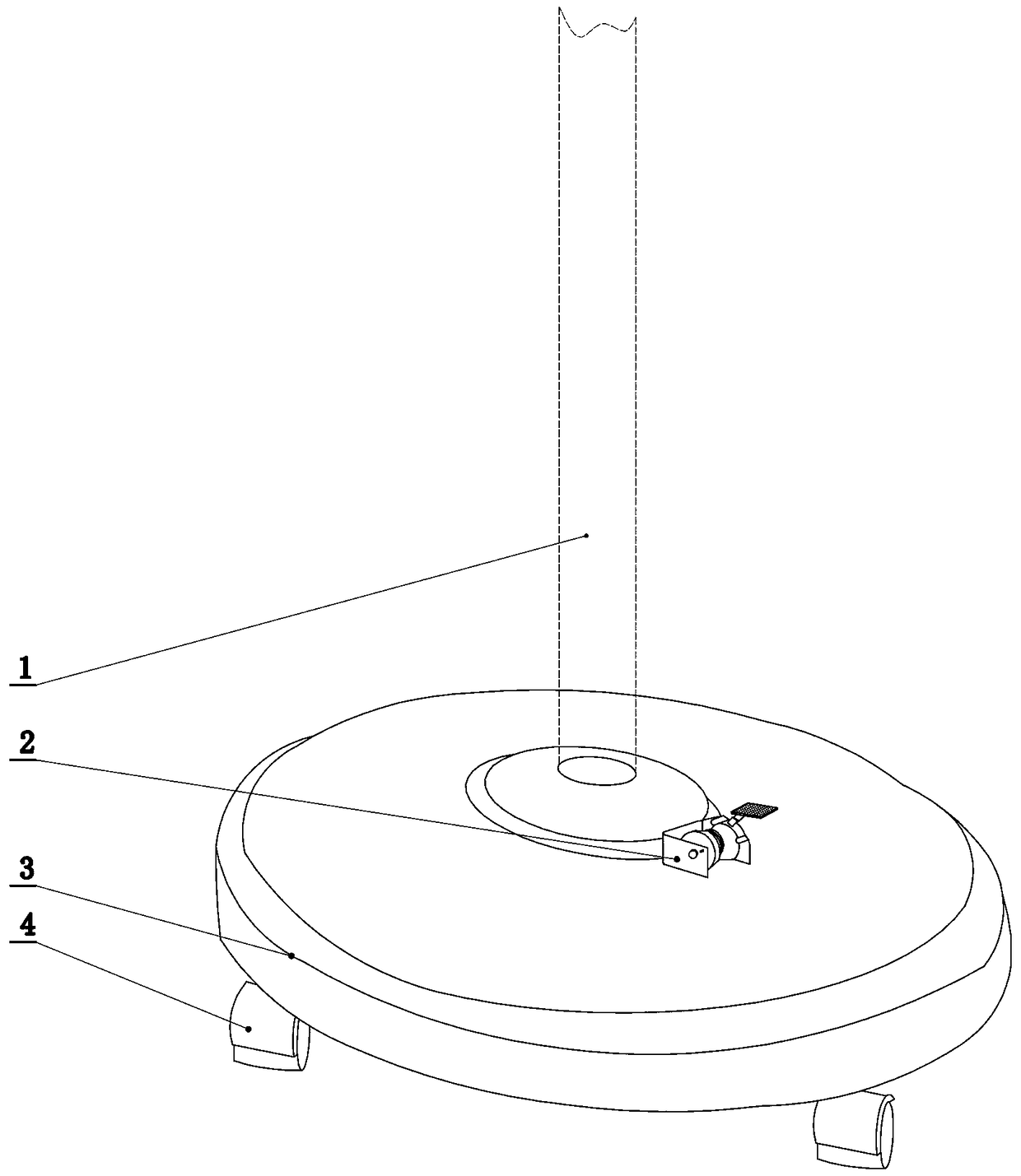
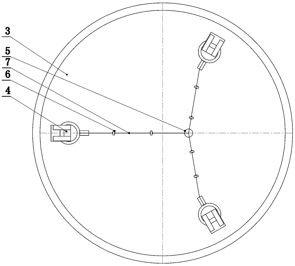
[0037] Below in conjunction with accompanying drawing, take floor fan base as example, the present invention will be further described. like Figure 1-2 As shown, a movable and locking equipment base includes: a base 3 with three base mounting holes 301 at the bottom, a universal wheel lifting assembly installed in the base mounting holes, and an inner sleeve for locking the universal wheel lifting assembly Tube locking assembly, locking winding wheels and swivel wheels for controlling base movement and locking status.

[0038] The universal wheel lifting assembly is formed by two inner and outer metal sleeves, and the outer sleeve 401 is installed on the bottom of the base through interference fit or through threads. The lifting sliding plate 406 on the upper end of the inner casing is located in the lifting chute 405 of the outer casing 401 , and the lifting compression spring 402 is installed on the inner casing 403 . The inner casing slides up and down along the lifting ...


PUM


Abstract

The invention discloses a movable and lockable equipment base. The movable and lockable equipment base comprises a base provided with at least three base mounting holes at the bottom, universal wheellifting modules mounted in the base mounting holes, inner sleeve locking modules for locking the universal wheel lifting modules, locking winding wheels for controlling moving and locking states of the base, and universal wheels arranged at the lower ends of the universal wheel lifting modules; the universal wheel lifting modules are sleeved by inner and outer sleeves; lifting pressure springs aremounted on the inner sleeves; the inner sleeves are provided with ratchet racks with upward tips; the universal wheels are mounted at the bottoms of the inner sleeves; the inner sleeve locking modules are mounted on the side walls of the outer sleeves, and comprise locking sleeves, locking rods with limiting ratchet racks at the inner ends, and return springs; the return springs are mounted between shaft shoulders at the middle parts of the locking rods and the outer ends of the locking sleeves; the limiting ratchet racks are engaged with the ratchet racks of the inner sleeves; the locking winding wheels are mounted on the upper surface of the base; and multiple thin steel wires wound on the winding wheels are connected with the outer ends of the corresponding locking rods.

Description

technical field [0001] The invention relates to a conveniently movable and reliable locking base, in particular to a conveniently movable floor fan base. Background technique [0002] For some equipment, it is not necessary to move frequently like the main unit of the vacuum cleaner, but sometimes it is necessary to change the working position, such as floor fans, small electric heaters and other household appliances. The comparatively common solution of existing home appliances is to install universal wheels. However, on the one hand, the contact area between the universal wheel and the ground is small, and it is not stable enough on smooth indoor surfaces such as marble surfaces and ceramic tiles; You need to find all the universal wheel brake pedals, and then press or step on them one by one. If only one or two of them are locked, other wheels can move, and the locking is unreliable. [0003] Floor fan is a common electrical product, which is widely used in homes, rest...

Claims


Application Information

Patent Timeline
Patent Type & Authority Applications(China)
IPC IPC(8): F16M3/00
CPCF16M3/00
Inventor 宋宜源李强
Owner 李强
Why Eureka
Try Eureka