Biomass gasification and combustion boiler with secondary ignition device

A technology of secondary ignition and ignition device, applied in the field of ignition system, can solve the problems of incomplete combustion of gasification gas and low furnace temperature.

Pending Publication Date: 2018-11-13
HEBEI UNIVERSITY OF SCIENCE AND TECHNOLOGY
View PDF3 Cites 1 Cited by
  • Summary
  • Abstract
  • Description
  • Claims
  • Application Information

AI Technical Summary

Problems solved by technology

[0004] In order to solve the problem of low furnace temperature at the initial stage of ignition and incomplete combustion of gasification gas in the current biomass gasification combustion boiler

Method used


Image

  • Biomass gasification and combustion boiler with secondary ignition device
  • Biomass gasification and combustion boiler with secondary ignition device

Examples


specific Embodiment approach 1

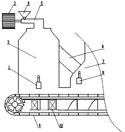
[0013] Specific implementation mode one: as figure 1 As shown, the biomass gasification combustion boiler with a secondary ignition device described in this embodiment includes a biomass gasification chamber 2, a combustion chamber 7, a primary ignition device 1, and a secondary ignition device 8; 4 enters the feeding dragon 5, the motor 3 drives the feeding dragon 4 to make the biomass fuel enter the biomass gasification chamber 2, the primary ignition device 1 starts, the biomass fuel is burned to generate gasification gas, and the gasification gas passes through the biomass gasification The connection device 6 between the chamber 2 and the combustion chamber 7 enters the combustion chamber 7, at this time, the secondary ignition device 8 is started, and when the temperature of the combustion chamber 7 reaches the requirement, the secondary ignition device 8 is turned off.

specific Embodiment approach 2

[0014] Specific implementation mode two: as figure 1 As shown, the secondary ignition device 8 described in this embodiment is located on the outer wall of the combustion chamber 7, at the outlet of the connecting device 6 between the biomass gasification chamber 2 and the combustion chamber 7; If there is not enough accumulation, the furnace temperature is low, and the temperature of the combustion chamber 7 cannot meet the requirements. The secondary ignition device 8 is activated to meet the temperature required for combustion and maintain stable combustion.

specific Embodiment approach 3

[0015] Specific implementation mode three: as figure 1 As shown, the primary ignition device 1 described in this embodiment is located at the lower end of the biomass gasification chamber 2. When the biomass fuel enters the biomass gasification chamber 2, the primary ignition device 1 is started, and the biomass fuel burns to generate gasification gas, which enters the To combustion chamber 7 combustion.


PUM


Abstract

The invention provides a biomass gasification and combustion boiler with a secondary ignition device, belongs to the technical field of boiler combustion, and solves the problem that by adoption of aconventional biomass boiler, the boiler temperature is low at the beginning of ignition, the ignition is difficult, black smoke is generated, and the combustion is unstable. According to the biomass gasification and combustion boiler, a primary ignition device is positioned at the lower end of a biomass gasifier and used for the ignition for biomass fuel gasification; and the secondary ignition device is positioned at the outlet of a connecting device arranged between a biomass gasification chamber and a combustion chamber, and used for the ignition of biomass gasification gas. The working process of the two ignition devices comprises the following steps: biomass fuel enters the biomass gasification chamber through a feeding screw conveyor, the primary ignition device is started, and the biomass gasification gas generated from the biomass gasification chamber enters the combustion chamber through the connecting device; at the time, the boiler temperature is low at the beginning of ignition and the secondary ignition device is started; and when the boiler temperature meets the temperature demand of the combustion chamber, the secondary ignition device is stopped. By adoption of thebiomass gasification and combustion boiler provided by the invention, the flame stabilization of the biomass combustion chamber can be guaranteed, and the incomplete combustion, caused by the low boiler temperature at the beginning of ignition, of biomass gasification gas can be effectively avoided.

Description

technical field [0001] The invention relates to an ignition system of a biomass gasification combustion boiler. A secondary ignition device is added to the system, which can solve the problem of incomplete combustion of gasification gas at the initial stage of ignition of the gasification combustion boiler, and belongs to the technical field of boiler combustion. Background technique [0002] The in-depth development and utilization of biomass, as one of the choices of large energy consumers in the future, can promote the development of society. Among them, biomass burning is the most traditional way. With the progress of society, in order to increase the combustion temperature of the furnace, the concept of gasification combustion boiler has been proposed, and has attracted the attention of academia and industrial enterprises. However, the current gasification and combustion boilers all use the ignition method of the gasification furnace, which causes problems such as low ...

Claims


Application Information

Patent Timeline
Patent Type & Authority Applications(China)
IPC IPC(8): F23B30/08F23B90/04F23K3/16F23Q13/00F23L1/02
CPCF23B30/08F23B90/04F23K3/16F23L1/02F23Q13/00
Inventor 李洪涛耿甜甜薛树旗纪运广赵亚珊常浩
Owner HEBEI UNIVERSITY OF SCIENCE AND TECHNOLOGY
Why Eureka
Try Eureka