
Rotational flow stress application/stamping combustion chamber

A stamping combustion chamber, swirl afterburning technology, applied in the direction of combustion chamber, continuous combustion chamber, combustion method, etc., can solve the problems of high difficulty in flame stable structure installation, low total pressure loss, difficult structure, etc., and achieve weight Lightening, small total pressure loss, good cooling effect

Active Publication Date: 2018-11-13
NANJING UNIV OF AERONAUTICS & ASTRONAUTICS
View PDF9 Cites 19 Cited by
  • Summary
  • Abstract
  • Description
  • Claims
  • Application Information

AI Technical Summary

Problems solved by technology

However, such a flame stabilization and propagation structure has certain disadvantages: 1. The installation difficulty of the flame stabilization structure is high, and it is easy to fail; 2. In a high temperature environment, it is very difficult to cool the structure; 3. Combustion efficiency and total pressure The loss is easily affected by the number of flame stabilizers, and it is necessary to maintain a low total pressure loss under the condition of considering high combustion efficiency; 4. Combustion efficiency depends on the inlet Mach number

Method used


Image

  • Rotational flow stress application/stamping combustion chamber
  • Rotational flow stress application/stamping combustion chamber
  • Rotational flow stress application/stamping combustion chamber

Examples


Embodiment Construction

[0039] The technical scheme of the present invention will be described in further detail below in conjunction with the accompanying drawings.

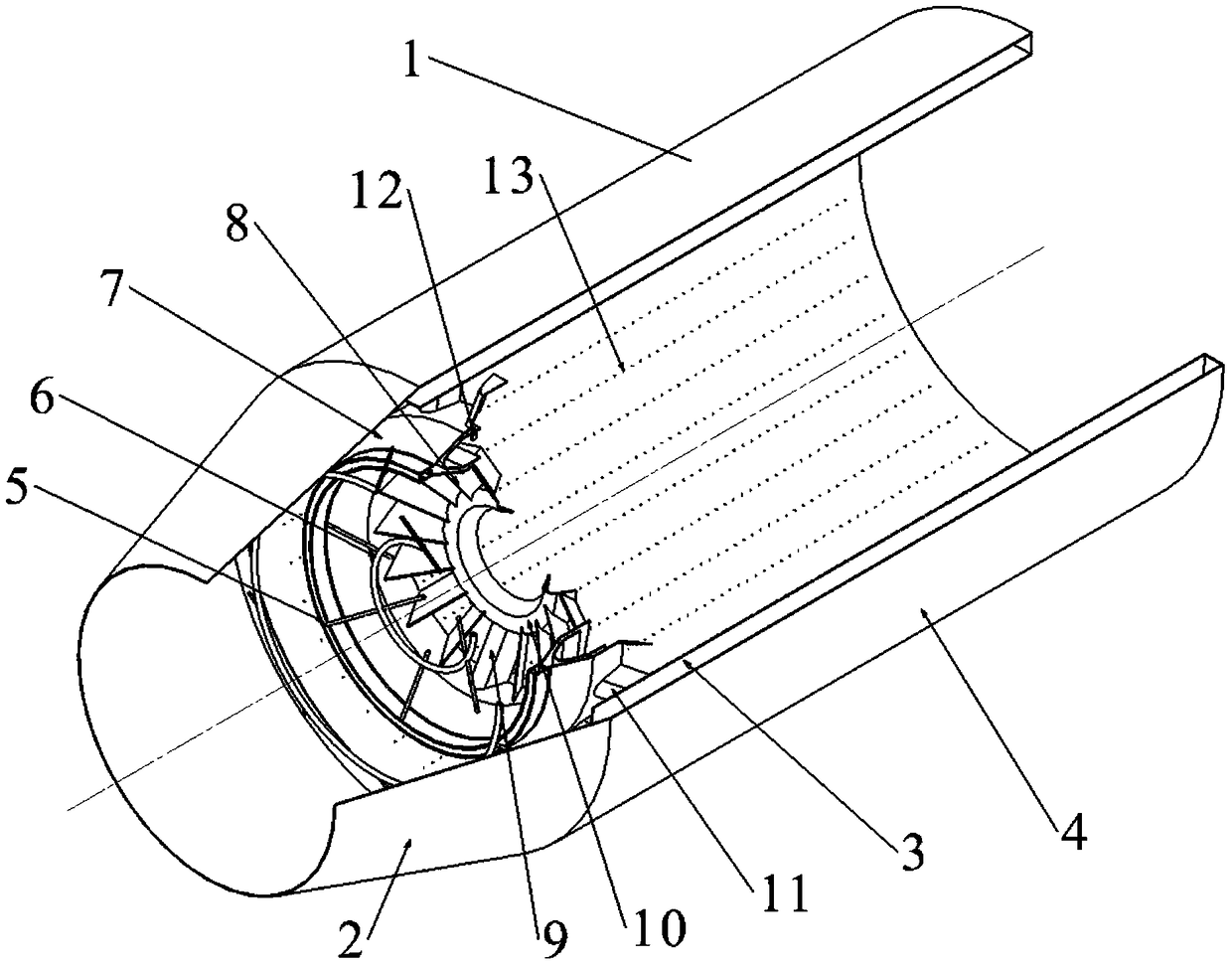
[0040] Such as figure 1 As shown, the swirl afterburner / ram combustion chamber 1 of the present invention is a full annular combustion chamber,

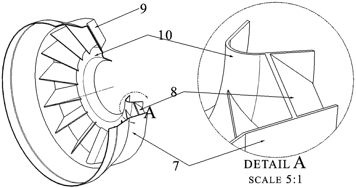
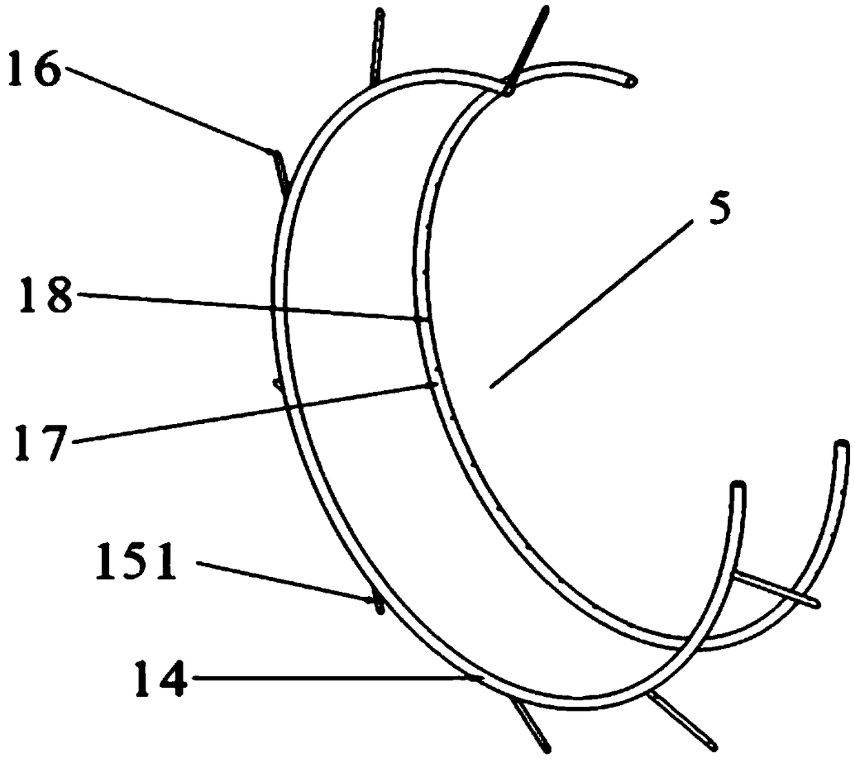
[0041] It mainly consists of diffuser 2, heat shield 3, outer casing 4, on-duty oil supply device 5, mainstream oil supply device 6, on-duty stabilizer 7, swirl vane 8, flame transfer groove 9, V-shaped stabilizer 10. It consists of a radial stabilizer 11 and a high-energy electric nozzle 12. The air flow enters the combustion chamber after being decelerated and pressurized by the diffuser 2, so as to facilitate the organization of combustion. The heat shield 3 is arranged in the outer casing 4, and the airflow flowing out from the diffuser 2 is divided into the main airflow and the external channel airflow for cooling through the heat shield 3, and several pairs of heat shield 3 walls are ...


PUM


Abstract

The invention discloses a rotational flow stress application / stamping combustion chamber and belongs to the technical field of rotational flow combustion of new concept aero-engines. In the structureof the combustion chamber, a diffuser carries out speed reduction and pressurization on airflow; a thermal insulating screen divides the incoming flow of a diffuser pipe into a main airflow and an outer duct airflow for cooling; a plurality of cooling holes are formed in the thermal insulating screen; a flame stabilizer transmits and stabilizes flame; a rotational flow blade is positioned in the flame stabilizer and forms a set included angle with the main airflow to rotate the downstream airflow; and an oil supply system comprises on-duty level oil supply, outer ring oil supply of a radial stabilizer and main combustion level oil supply and adopts the oil supply manners of combination of a direct-injection type fuel spray nozzle and an annular oil pipe, and a radial oil pipe of a main oilpipe. Compared with a traditional combustor, as the rotational flow combustion manner is adopted, the flame propagation velocity is not affected by pressure; in addition, the subregion oil supply manner is adopted, so that the oil and gas are mixed more fully, combustion is more efficient and stable, and pollution is less; and moreover, the flame transferring device of the flame stabilizer is eliminated, so that the structure of the combustion chamber is simplified, the length of the combustion chamber is shortened and the weight of the combustion chamber is reduced.

Description

technical field [0001] The invention relates to a swirl afterburner / ramjet combustion chamber, which is mainly used as an afterburner or ramjet combustion chamber of an aero-engine, and belongs to the technical field of new-concept aero-engine swirl combustion. Background technique [0002] The afterburner has always occupied a very important position in the field of military aircraft. It can increase the lift of the turbofan engine by 60% to 70%, and the lift of the turbojet engine by 40% to 50%. At present, there are basically two types of oil-gas mixed combustion methods in the afterburner: 1. "mix first and then burn", and 2. "combust while mixing". [0003] The flame stabilizer is located at the outlet of the diffuser. Generally, oil is supplied upstream of the flame stabilizer, and the recirculation zone downstream of the stabilizer organizes combustion. The airflow decelerates rapidly after entering the diffuser, and then forms a recirculation zone at the end of the ...

Claims


Application Information

Patent Timeline
Patent Type & Authority Applications(China)
IPC IPC(8): F23R3/38
CPCF23R3/38
Inventor 何小民黄亚坤魏杰立周毅
Owner NANJING UNIV OF AERONAUTICS & ASTRONAUTICS
Learn More