
Method and system for testing gap values of workpieces on basis of laser light

A gap and workpiece technology, applied in the field of measuring workpiece gap value based on laser, can solve the problems of low measurement accuracy and insufficient automatic judgment ability, and achieve the effect of high measurement accuracy

Active Publication Date: 2018-11-13
UNIV OF ELECTRONICS SCI & TECH OF CHINA
View PDF5 Cites 10 Cited by
  • Summary
  • Abstract
  • Description
  • Claims
  • Application Information

AI Technical Summary

Problems solved by technology

[0005] The purpose of the present invention is to overcome the deficiencies of the prior art and provide a method and system for measuring the gap value of workpieces based on laser. The method is used to solve the problems of low measurement accuracy and insufficient automatic judgment ability existing in the existing gap measurement

Method used


Image

  • Method and system for testing gap values of workpieces on basis of laser light
  • Method and system for testing gap values of workpieces on basis of laser light
  • Method and system for testing gap values of workpieces on basis of laser light

Examples


Embodiment 1

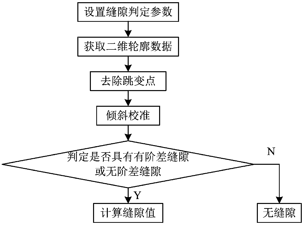
[0076] When two objects are close but not in direct contact, the distance between them is called the gap. The calculation of the gap also includes two parts, which are the judgment of the gap and the calculation of the size of the gap.

[0077] The idea of ​​gap judgment and gap size calculation in the present invention is: the step difference gap judgment method is to use the gap judgment parameters to judge whether there are three consecutive planes in the two-dimensional contour data measured by the laser line scanning sensor, and the middle plane is located on the left and right planes Below , if it exists, the object has a gap with a step difference, and the size of the gap is equal to the length value of the middle plane in the contour data, that is, the intersection point B of the first plane and the second plane 1 and the intersection point C of the second plane and the third plane 1 The absolute value of the difference of the x-axis values. The non-step difference g...

Embodiment 2

[0134] Based on the above method, the present invention also provides a system for testing workpiece gap value based on laser, including:

[0135] The parameter setting module is used to set parameters, and the parameters include gap determination parameters, de-trip point parameters and tilt calibration parameters;

[0136] Workpiece contour acquisition module: used to scan the measured workpiece with a laser sensor, obtain the measured workpiece contour data, and analyze the measured workpiece contour data into two-dimensional contour data, the two-dimensional contour data is X containing N collection points Axis data and Z-axis data containing N collection points, where N is the total number of all collection points in the measured workpiece contour data;

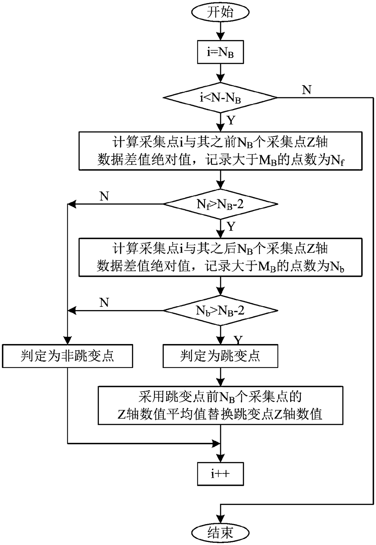
[0137] The trip point removal module is used to perform trip point removal processing on the two-dimensional contour data according to the trip point removal parameter;

[0138] An inclination calibration module, config...


PUM


Abstract

The invention discloses a method and a system for testing gap values of workpieces on the basis of laser light. The method includes a process for determining gaps with jump and a process for determining gaps without jump. The process for determining the gaps with the jump includes that whether three continuous planes are available in two-dimensional contour data measured by laser line scanning sensors or not is judged by the aid of gap determination parameters, the middle plane is positioned below the left plane and the right plane, the gaps with the jump are reserved in objects if the three continuous planes are available in the two-dimensional contour data, and the sizes of the gaps are equal to a length value, namely, an absolute value of a difference value of X-axis numerical values ofan intersection B1 of the first plane and the second plane and an intersection C1 of the second plane and the third plane, of the middle plane in the contour data. The process for determining the gaps without the jump includes carrying out point-by-point comparison to judge whether X-axis numerical values of every two adjacent points are larger than gap distance determination parameters or not; determining that the gaps without the jump are reserved in the tested objects if the distance D between every two adjacent points is larger than the gap determination parameters. The gaps without the jump are larger than or equal to the distances D. The method and the system have the advantage that the problems of lower measurement accuracy and insufficient automatic judgment ability of gap measurement at present can be solved by the aid of the method and the system.

Description

technical field [0001] The invention belongs to the technical field of test and measurement, and in particular relates to a method and system for testing the gap value of workpieces based on laser. Background technique [0002] For the detection of workpiece gaps, the traditional method is to use calipers and feeler gauges for manual testing. During the test, observe with the naked eye whether there is a gap in the shape of the workpiece or the splicing part, and then select a combination of caliper and feeler gauge that meets the test range and measurement accuracy by observing the approximate size of the gap. This test method has complicated test steps, low test efficiency, and consumes a lot of manpower in the test process. The test results have a large human error. Moreover, the caliper and feeler gauge are easy to wear the workpiece under test during the test, which cannot meet the non-destructive and rapid measurement of the gap. [0003] Among various new test meth...

Claims


Application Information

Patent Timeline
IPC IPC(8): G01B11/14
CPCG01B11/14
Inventor 胡学海胡文翔黄杨笃优陈俊
Owner UNIV OF ELECTRONICS SCI & TECH OF CHINA
Learn More