Eureka AIR delivers breakthrough ideas for toughest innovation challenges, trusted by R&D personnel around the world.

Optical fiber sensor, manufacturing method thereof and motion sensing device

An optical fiber sensor and optical fiber technology, applied in the sensor field, can solve the problems of limited sensitivity and application range, weak anti-electromagnetic interference ability, etc., and achieve the effect of high sensitivity, small volume and mass, easy and distributed measurement

Active Publication Date: 2018-11-13
BOE TECH GRP CO LTD +1
View PDF13 Cites 6 Cited by
  • Summary
  • Abstract
  • Description
  • Claims
  • Application Information

AI Technical Summary

Problems solved by technology

This phenomenon can be used to make level, speed, acceleration sensors, etc., but the principles of these sensors in related technologies are mostly based on the Hall effect, and the ability to resist electromagnetic interference is weak, and the device itself is a source of interference, which makes its sensitivity and application range limited. certain restrictions

Method used


Image

  • Optical fiber sensor, manufacturing method thereof and motion sensing device
  • Optical fiber sensor, manufacturing method thereof and motion sensing device
  • Optical fiber sensor, manufacturing method thereof and motion sensing device

Examples


Embodiment Construction

[0035] In order to make the purpose, technical solution and advantages of the present disclosure clearer, the implementation manners of the present disclosure will be further described in detail below in conjunction with the accompanying drawings. Apparently, the described embodiments are some of the embodiments of the present disclosure, not all of them. Based on the described embodiments of the present disclosure, all other embodiments obtained by persons of ordinary skill in the art without creative effort fall within the protection scope of the present disclosure. Unless otherwise defined, the technical terms or scientific terms used in the present disclosure shall have the usual meanings understood by those skilled in the art to which the present disclosure belongs. "First", "second" and similar words used in the present disclosure do not indicate any order, quantity or importance, but are only used to distinguish different components. "Comprising" or similar words mean ...


PUM


Abstract

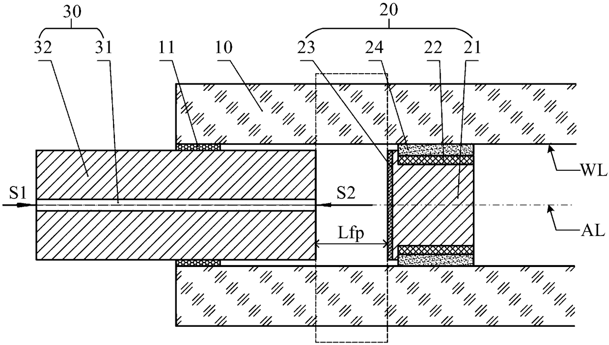
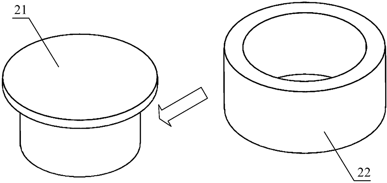
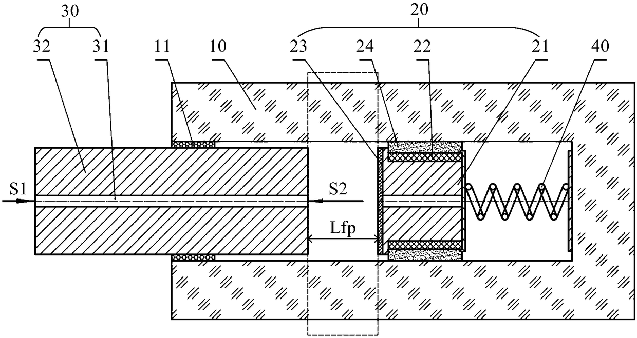
The invention provides an optical fiber sensor, a manufacturing method thereof and a motion sensing device, and relates to the field of sensors. The optical fiber sensor comprises a sleeve, a magneticmass and a sensing optical fiber, wherein the magnetic mass is located in the sleeve, and magnetic fluid is adsorbed on the outer surface, opposite to the inner wall of the sleeve, of the magnetic mass, so that the magnetic mass can float in the sleeve and move along the axis of the sleeve; one end of the sensing optical fiber penetrates into a first port of the sleeve, a reflecting plane is arranged on the outer surface, opposite to the sensing optical fiber, of the magnetic mass, based on the sensing optical fiber, incident light can be supplied to the reflecting plane, and measurement light from the reflecting plane can be received. The high-sensitivity sensor can be achieved based on second-order suspension action of the magnetic fluid, and the sensor has the advantages of being simple in structure and small in volume and mass, facilitating remote measurement and distributed measurement, and the like.

Description

technical field [0001] The present disclosure relates to the field of sensors, in particular to an optical fiber sensor, a manufacturing method thereof, and a motion sensing device. Background technique [0002] Magnetic fluid is a liquid magnetic material, which has both the fluidity of liquid and the physical characteristics of some solid magnetic materials. The magnetic fluid has a second-order levitation effect, so that the permanent magnet can be suspended in the magnetic fluid. This phenomenon can be used to make level, speed, acceleration sensors, etc., but the principle of these sensors in the related art is mostly based on the Hall effect, the ability to resist electromagnetic interference is weak, and the device itself is a source of interference, which makes its sensitivity and application range limited. certain restrictions. Contents of the invention [0003] The disclosure provides an optical fiber sensor, a manufacturing method thereof, and a motion sensing...

Claims


Application Information

Patent Timeline
Patent Type & Authority Applications(China)
IPC IPC(8): G01D5/353G01D21/02
CPCG01D5/35312G01D21/02G01P15/093G01D5/268G01P13/00
Inventor 刘宇翟明傅晓亮
Owner BOE TECH GRP CO LTD
Why Eureka
Eureka Blog
Learn More