Frequency modulated continuous wave radar level meter of 120 GHz and distance measurement method

A technology of frequency modulation continuous wave and radar level meter, which is applied in the field of level meter, can solve the problems of unfavorable small tank measurement, small blind area, high-precision measurement, etc., and achieve the effect of solving large blind area

Active Publication Date: 2018-11-13
福州盛博电子有限公司
View PDF6 Cites 14 Cited by
  • Summary
  • Abstract
  • Description
  • Claims
  • Application Information

AI Technical Summary

Problems solved by technology

[0007] The frequency modulation radar currently on the market generally has a frequency of 24GHz~26GHz or 78GHz~80GHz, and the frequency modulation bandwidth is up to 1GHz, which is not conducive to the measurement of small tanks, and cannot meet the requirements of small blind spots and high-precision measurement.

Method used


Image

  • Frequency modulated continuous wave radar level meter of 120 GHz and distance measurement method
  • Frequency modulated continuous wave radar level meter of 120 GHz and distance measurement method
  • Frequency modulated continuous wave radar level meter of 120 GHz and distance measurement method

Examples


Embodiment 1

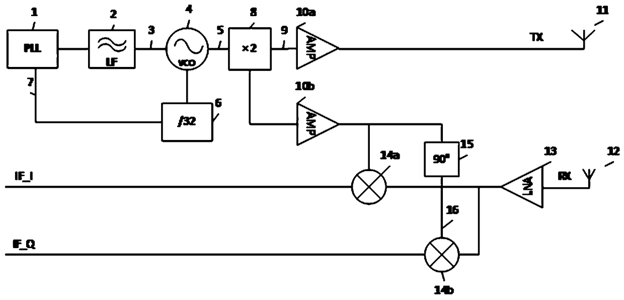
[0046] This embodiment provides a 120 GHz frequency modulation continuous wave radar level gauge, including a frequency modulation module, an intermediate frequency signal conditioning and sampling module, an echo signal processing module, a threshold curve generation module and a spectrum estimation module.

[0047] refer to figure 1, The frequency modulation module includes a phase-locked loop 1, a loop filter (LF) 2, a voltage-controlled oscillator (VCO) 4, a 32-fold frequency divider 6, a 90° phase shifter 15, a 2-frequency multiplier 8, and the first power Amplifier 10a, second power amplifier 10b, low noise amplifier (LNA) 13, first mixer 14a, second mixer 14b, transmitting antenna 11 and receiving antenna 12; among them, phase-locked loop 1, loop filter (LF) 2, voltage-controlled oscillator (VCO) 4, 2 frequency multiplier 8, and first power amplifier 10a are electrically connected in sequence; the input end of the 32-fold frequency divider 6 is connected to the other ch...

Embodiment 2

[0060] On the basis of Embodiment 1, this embodiment provides a distance measuring method based on a radar level gauge, the method comprising:

[0061] S01. Generate the difference frequency in-phase signal IF_I of the transmission frequency TX and the reception frequency RX, and the difference frequency quadrature signal IF_Q of the TX and RX; wherein, the values ​​of the transmission frequency TX and the reception frequency RX are 120GHz~130GHz;

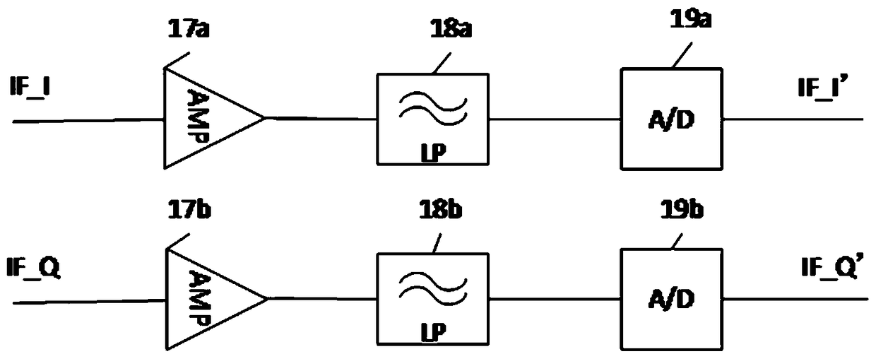
[0062] S02. After sequentially amplifying the difference frequency in-phase signal IF_I and the difference frequency quadrature signal IF_Q, low-pass filtering, and analog-to-digital conversion, generate digitized intermediate frequency quadrature signals IF_I' and IF_Q';

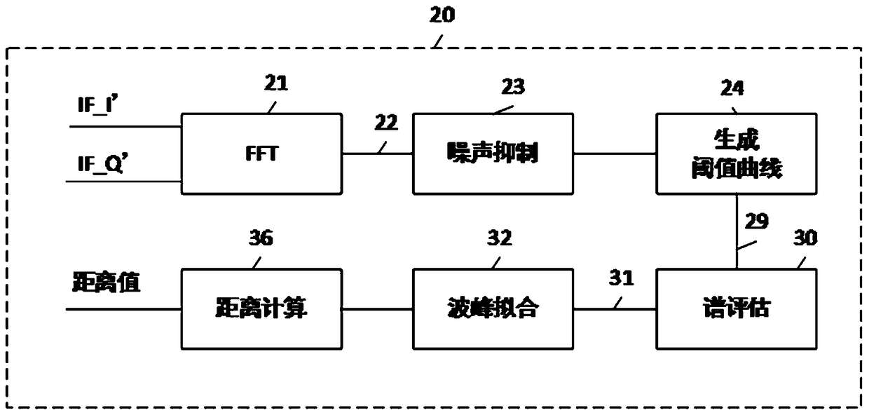
[0063] S03. Convert the intermediate frequency quadrature signals IF_I' and IF_Q' from time domain signals into spectrum curves through complex fast Fourier transform;

[0064] S04. Dynamically generate a threshold curve according to the frequency spectrum curve...


PUM


Abstract

The invention discloses a frequency modulated continuous wave radar level meter of 120 GHz and a distance measurement method. The radar level meter comprises a frequency modulating module, an intermediate frequency signal conditioning and sampling module, an echo signal processing module, a threshold value curve generation module and a spectrum estimation module; the frequency modulating module isarranged to be used for generating a difference frequency in-phase signal IF_I and a difference frequency orthogonal signal IF_Q of sending frequency TX and receiving frequency RX; the intermediate frequency signal conditioning and sampling module is arranged to be used for sequentially processing the difference frequency in-phase signal IF_I and the difference frequency orthogonal signal IF_Q togenerate digitalized intermediate frequency orthogonal signals IF_I' and IF_Q'; the echo signal processing module is arranged to be used for converting the intermediate frequency orthogonal signals IF_I' and IF_Q' as time domain signals into a frequency spectrum curve; the threshold value curve generation module is arranged to be used for dynamically generating a threshold value curve according to the generated frequency spectrum curve so that multiple echoes can be obtained. The frequency modulated continuous wave radar level meter of 120 GHz has the advantages that the area of a measurementblind region is small, and precision is high.

Description

technical field [0001] The invention relates to a level gauge, in particular to a 120GHz frequency modulation continuous wave radar level gauge. Background technique [0002] In the implementation process of industrial process control and factory automation, it is very important to be able to measure the height of material level stably and reliably. Radar level gauges are rapidly gaining popularity due to their non-contact, accurate measurement, and easy maintenance. [0003] There are two types of radar level gauges: pulse radar level gauge and frequency modulation radar level gauge: [0004] One is the pulse radar level gauge, which calculates the target distance by measuring the time difference between sending and receiving microwave pulses. When the target distance is only a few meters, the time difference between sending microwave pulses and reflecting microwave pulses is only a few nanoseconds, and time expansion technology must be used The time difference of the nan...

Claims


Application Information

Patent Timeline
Patent Type & Authority Applications(China)
IPC IPC(8): G01F23/284
CPCG01F23/284
Inventor 黄高昂谢万荣宋红伟刘银军
Owner 福州盛博电子有限公司
Why Eureka
Try Eureka