Target tracking method under arbitrary linear constraints
A target tracking and straight line technology, applied in the field of target tracking, can solve problems such as modeling and state estimation methods without arbitrary straight line constraints
- Summary
- Abstract
- Description
- Claims
- Application Information
AI Technical Summary
Problems solved by technology
Method used
Image
Examples
Embodiment 1
[0093] A method for tracking a target under arbitrary straight line constraints provided by an embodiment of the present invention includes the following steps:
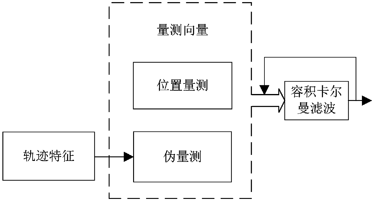
[0094] S1. Obtain the target position measurement information from the observation radar to construct a measurement vector, which includes the distance measurement of the target relative to the origin of the observation radar coordinate system and azimuth measurement
[0095] Obtaining target position measurement information from the observation radar during the tracking process is an existing technology, how the observation radar obtains this information, and how the method of the embodiment of the present invention obtains this information from the radar, those skilled in the art can adopt the existing technology It can be realized in various ways, and no matter which method is adopted, it is within the protection scope of the present invention.
[0096] S2. Use the state vector x of the target in the past k A...
Embodiment 2
[0102] Embodiment 2 is basically the same as Embodiment 1, and the similarities will not be described in detail. The difference lies in:
[0103] In step S2 of this embodiment, the target motion model under the Cartesian coordinate system is established, and the state equation of the target motion model is:
[0104] x k+1 = Φ k x k +Γ k v k
[0105] where x k is the state vector at time k, and the subscript is the corresponding time, including the position component x along the x and y directions at time k k 、y k , and the velocity component x k+1 is the state vector at time k+1; Φ k is the state transition matrix; v k is the process noise vector, assuming that the process noise is Gaussian white noise with known zero mean variance, and its process noise covariance matrix is cov(v k )=Q k ≥0; k is the noise distribution matrix.
[0106] Preferably, in the step S1, the near-constant velocity model (NCV) is used as the target motion model in the linear moving t...
Embodiment 3
[0118] The third embodiment is basically the same as the second embodiment, and the similarities will not be repeated. The difference lies in:
[0119] In step S3 of this embodiment, the augmented state is used to construct a pseudo-measurement to describe any linear constraint relationship, and the pseudo-measurement in the Cartesian coordinate system is obtained as:
[0120]
[0121] It can be seen that only the state components of the target position and velocity at time k and k-1 can be used to give a complete description of the constraint relationship. In fact, as long as d≥1, the description of the constraint relationship can be obtained through the above formula.
[0122] Preferably, the pseudo-measurement is augmented into the measurement vector, and the augmented measurement equation is obtained as:
[0123]
[0124] The corresponding measurement noise covariance matrix is:
[0125]
[0126] in, is the measurement vector at time k, is a function that ch...
PUM
 Abstract
Description
Claims
Application Information
 - R&D
- Intellectual Property
- Life Sciences
- Materials
- Tech Scout
- Unparalleled Data Quality
- Higher Quality Content
- 60% Fewer Hallucinations
Browse by: Latest US Patents, China's latest patents, Technical Efficacy Thesaurus, Application Domain, Technology Topic, Popular Technical Reports.
© 2025 PatSnap. All rights reserved.Legal|Privacy policy|Modern Slavery Act Transparency Statement|Sitemap|About US| Contact US: help@patsnap.com


