Optical characteristic measuring system and application method thereof

A technology for measuring systems and optical characteristics, applied in the field of optical testing, which can solve problems such as high demand for detector height ranges

Active Publication Date: 2018-11-13
BEIJING INST OF ENVIRONMENTAL FEATURES
View PDF6 Cites 6 Cited by
  • Summary
  • Abstract
  • Description
  • Claims
  • Application Information

AI Technical Summary

Problems solved by technology

The disadvantage of this method is: if the detector is far away from the detect

Method used


Image

  • Optical characteristic measuring system and application method thereof
  • Optical characteristic measuring system and application method thereof
  • Optical characteristic measuring system and application method thereof

Examples


Embodiment 1

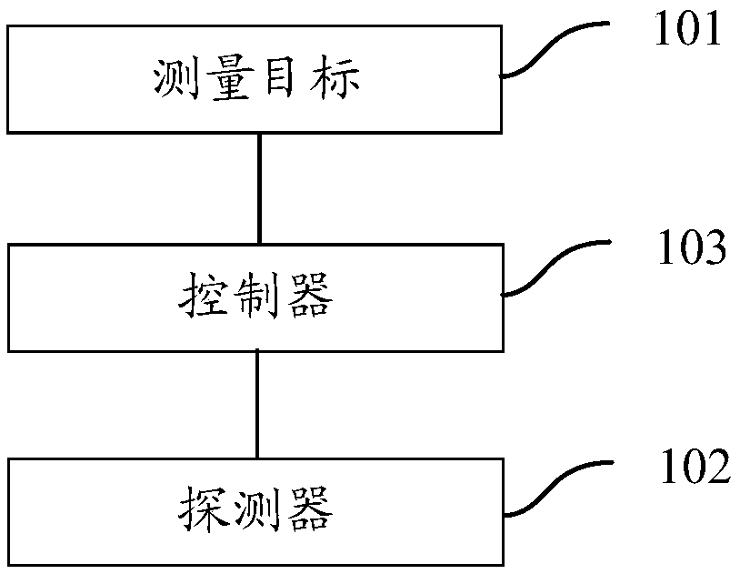
[0094] Such as figure 1 As shown, an optical characteristic measurement system provided by an embodiment of the present invention includes: a measurement target 101, a detector 102, and a controller 103; wherein,

[0095] The measurement target 101 and the detector 102 are located in the same horizontal plane;

[0096] The controller 103 is configured to receive a measurement instruction, determine the target motion posture of the measurement target 101 and the target position information of the detector 102 according to the target incident angle and target detection angle carried in the measurement command; The movement posture of the target is controlled to adjust the movement posture of the measurement target 101; according to the target position information, the detector 102 is controlled to move;

[0097] The measurement target 101 is used to adjust its own movement posture under the control of the controller 103;

[0098] The detector 103 is configured to move to a tar...

Embodiment 2

[0101] Embodiment 2 is basically the same as Embodiment 1, and the similarities will not be described in detail. The difference lies in:

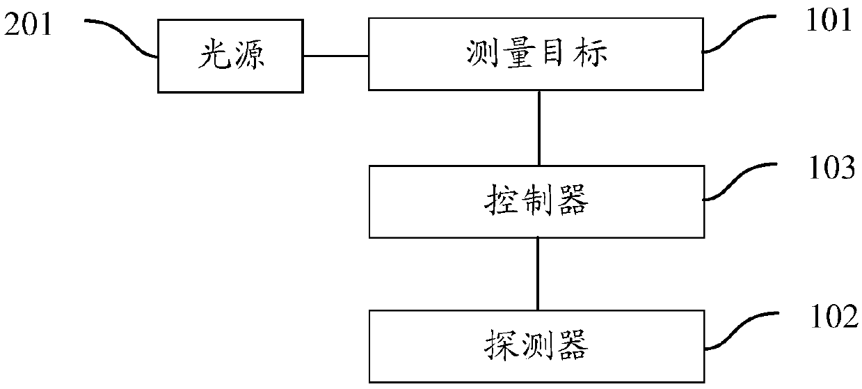
[0102] Such as figure 2 As shown, the optical characteristic measurement system may further include: a light source 201; wherein,

[0103] The light source 201, the measurement target 101 and the detector 102 are located in the same horizontal plane;

[0104] The light source 201 is configured to emit incident rays to the measurement target 101;

[0105] The detector 102 is configured to emit a detection line to the measurement target 101, and measure the measurement target 101 according to the detection line reflected by the measurement target 101;

[0106] The measurement target 101 is further configured to reflect the detection line to the detector 102 according to the detection line;

[0107]The controller 103 is configured to determine an incident azimuth angle and an incident elevation angle according to the target incident angle ...

Embodiment 3

[0114] The third embodiment is basically the same as the second embodiment, and the similarities will not be repeated. The difference lies in:

[0115] Such as Figure 7 As shown, the measurement target 101 includes: a measurement target body 1011, a central axis 1012, an upper arc motion mechanism 1013, a turning mechanism 1014 and a lower arc motion mechanism 1015; wherein,

[0116] The center of the measurement target body 1011 is connected to one end of the central axis 1012;

[0117] The other end of the central shaft 1012 is connected with the first slider in the upper arc motion mechanism 1013;

[0118] The slewing mechanism 1014 is arranged between the upper arc motion mechanism 1013 and the lower arc motion mechanism 1015;

[0119] The turning mechanism 1014 is connected with the second slide block in the lower arc movement mechanism 1015 , and the turning mechanism 1014 is connected with the upper arc movement mechanism 1013 .

[0120] Through the above settings, ...


PUM


Abstract

The invention relates to an optical property measurement system and an application method thereof. The system comprises a measurement target, a detector and a controller, wherein the measuring targetand the detector are located in the same horizontal plane; the controller is used for receiving the measuring instruction, determining the target motion gesture of the measurement target and the target position information of the detector according to the target incidence angle and the target detection angle carried in the measurement instruction; controlling the measurement target to adjust the motion posture according to the target motion posture,; according to the target position information, the detector is controlled to move; the measurement target is used for adjusting the motion postureof the controller under the control; the detector is used for moving to a target position corresponding to the target position information under the control of the controller, and measuring the measurement target after the movement posture is adjusted at the target position. According to the scheme, the height adjustment range of the detector can be reduced, the space occupied by the optical property measurement system is reduced, and the construction cost of the optical property measuring system is reduced.

Description

technical field [0001] The invention relates to the technical field of optical testing, in particular to an optical characteristic measuring system and an application method thereof. Background technique [0002] In the target optical characteristic measurement system, in order to achieve optical characteristic measurement in different illumination directions and observation directions, it is generally necessary to change the position of the detector or the measurement target or the elevation angle of the detector in the detection direction. [0003] At present, the measurement of optical characteristics in different observation directions is generally achieved by changing the position of the detector or the elevation angle in the detection direction without moving the light source and the measurement target. In the target optical characteristic measurement system, the light source is generally set in the horizontal plane, and the detector is set above the horizontal plane, ...

Claims


Application Information

Patent Timeline
IPC IPC(8): G01S17/42G01S7/497
CPCG01S7/497G01S17/42
Inventor 范小礼王静苏必达武敬力
Owner BEIJING INST OF ENVIRONMENTAL FEATURES
Why Eureka
Try Eureka