Submarine flight node electromagnetic receiver

A receiver and electromagnetic technology, applied in the field of marine geophysical exploration, can solve the problems of push-up operation cost, offshore operation time cost, and many ships occupied by launching and recycling, so as to reduce operation cost, save the salvage process, and reduce operation cost. Effect

Inactive Publication Date: 2018-11-13
CHINA UNIV OF GEOSCIENCES (BEIJING)
View PDF4 Cites 6 Cited by
  • Summary
  • Abstract
  • Description
  • Claims
  • Application Information

AI Technical Summary

Problems solved by technology

[0005] The shortcomings of the existing operation methods are: ① low efficiency, and the offshore operation time is mainly spent on instrument launch and recovery; ② the station layout accuracy is low, and when it sinks freely, it is vulnerable to the impact of ocean currents, and the actual bottom point is different from the expected bottom point. There is often a large offset, the depth of the water is about the greater the gap may be, and the low accuracy of the station layout is not conducive to the inversion and interpretation of the anomaly in the later data processing; ③ Random sensor orientation: due to the free sinking of the receiver, the sensor orientation is randomly arranged, Requires later data processing and rotation correction; ④Environmental impact, a cement block is left on the seabed every time it is put in. The cement block is made of concrete and cannot be degraded naturally; ⑥Safety risks. Insufficient judgment of the micro-topography of the seabed will make it difficult for the seabed electromagnetic receiver to float normally, and there is a risk of loss of instruments and valuable data.
[0006] In summary, marine electromagnetic methods are in strong demand in the oil and gas exploration market, and existing submarine electromagnetic receivers have deficiencies in deployment accuracy, operating efficiency, operating cost, environmental impact, and safety. It is necessary to carry out relevant technical research to promote marine electromagnetic methods. Technical equipment development

Method used


Image

  • Submarine flight node electromagnetic receiver
  • Submarine flight node electromagnetic receiver
  • Submarine flight node electromagnetic receiver

Examples


Embodiment Construction

[0029] The present invention will be further described below in conjunction with the accompanying drawings and embodiments.

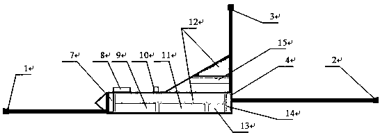
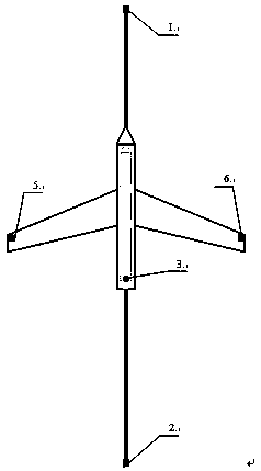
[0030] Such as figure 1 As shown in -5, an electromagnetic receiver of a submarine flight node in the present invention includes an electromagnetic data acquisition module and an autonomous underwater vehicle, and the autonomous underwater vehicle includes a power device and an auxiliary device; wherein the electromagnetic data acquisition module includes electrodes, Magnetic field sensor 15 and data acquisition cabin 9; Power device includes altimeter 7, power control cabin 11 and propeller 14; Auxiliary device includes sonar 13, underwater acoustic communication module 8 and floating body 12; Electromagnetic data acquisition is installed on autonomous underwater vehicle module.

[0031] The electromagnetic receiver of the seabed flight node has 6 electrodes in its electromagnetic data acquisition module, which are front electrode one 1, tail electrod...


PUM


Abstract

The invention discloses a submarine flight node electromagnetic receiver. The receiver comprises an electromagnetic data acquisition module and an autonomous underwater vehicle, wherein the autonomousunderwater vehicle comprises a power device and an auxiliary device; the electromagnetic data acquisition module comprises an electrode, a magnetic field sensor and a data acquisition cabin; the power device comprises an altimeter, a power control cabin and a propeller; the auxiliary device comprises sonar, an underwater acoustic communication module and a floating body; the electromagnetic dataacquisition module is mounted on the autonomous underwater vehicle. The submarine flight node electromagnetic receiver inherits the characteristics of large dynamic range, low noise and low power consumption of existing submarine electromagnetic receivers, realizes accurate station arrangement of marine operations, controllable sensor orientation, independent and rapid switching and arranging of stations with marine electromagnetic methods, has the advantages of environmental friendliness, safety, high efficiency and low cost, and is one of the development directions of marine electromagneticexploration equipment.

Description

technical field [0001] The invention relates to technical equipment in the field of marine geophysical exploration, in particular to a high-efficiency, low-cost marine electromagnetic exploration equipment for underwater operations. Background technique [0002] At present, the marine electromagnetic method is an emerging marine geophysical method, which is widely used in the geophysical exploration field of mineral resources such as seabed oil and gas exploration, hydrate investigation, etc. In the field of geosciences, underwater target detection, early warning and other defense fields, tsunami early warning, marine electromagnetic environment research and other physical ocean fields. Among them, the field of submarine oil and gas exploration is the most popular. The marine electromagnetic method is based on the electrical difference between the oil and gas target and the surrounding rock medium below the seabed. The electromagnetic field signal carrying the electrical inf...

Claims


Application Information

Patent Timeline
Patent Type & Authority Applications(China)
IPC IPC(8): G01V3/08
CPCG01V3/081
Inventor 陈凯邓明王猛
Owner CHINA UNIV OF GEOSCIENCES (BEIJING)
Why Eureka
Try Eureka