A controller of a transformer cooler and its control method

A technology of coolers and transformers, which is applied to the cooling of transformers/inductors and the use of electric means for temperature control, etc., can solve the problems of major transformer tripping accidents, large current carrying contactors, inconvenient maintenance personnel, etc., and achieves strong versatility, Precise protection and maintenance effects

Active Publication Date: 2020-12-18
陕西金源自动化科技有限公司
View PDF5 Cites 0 Cited by
  • Summary
  • Abstract
  • Description
  • Claims
  • Application Information

AI Technical Summary

Problems solved by technology

[0002] At present, the coolers of domestic transformers use AC contactors as the main power actuators. After complex electrical connections, they are assembled into traditional electromagnetic and PLC intelligent cooling control cabinets for centralized control, and all coolers share a dual power switching circuit. In this way, the contactor of the dual power supply circuit carries a large current and is easy to generate heat, resulting in a high failure rate. When the fault needs to be replaced, due to the close connection with other circuits, it is easy to cause the failure of the cooler to stop completely, which will cause the transformer to trip and cause serious damage. Accidents; thermal relays are used as motor protection, the protection accuracy is not high, and the versatility is not strong, resulting in more types of spare parts, which brings inconvenience to management, and when troubleshooting occurs, it takes a lot of time and time to replace devices Most of them have to be operated in a power outage, which brings inconvenience to maintenance personnel and many other problems

Method used


Image

  • A controller of a transformer cooler and its control method
  • A controller of a transformer cooler and its control method
  • A controller of a transformer cooler and its control method

Examples


Embodiment Construction

[0042] The present invention will be further described in detail below in conjunction with specific embodiments, which are explanations of the present invention rather than limitations.

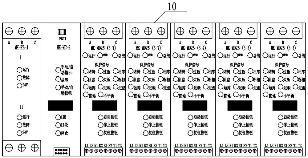
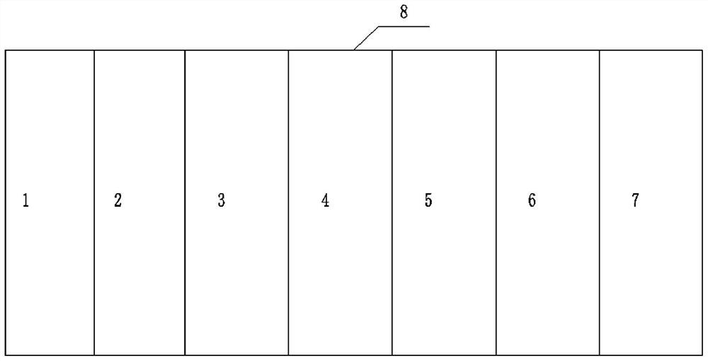
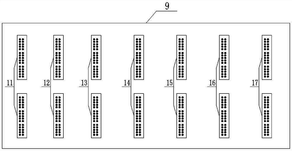
[0043] The controller of the transformer cooler of the present invention includes a chassis slot 1-7, a backboard 9 and a functional module; the functional module is plugged into the backplane 9 through the chassis slot 1-7.

[0044] Among them, the functional modules include: a dual power supply switching module 21 , a motor starting and protection module 23 and a main control module 22 .

[0045] In this preferred example, such as figure 1 As shown, the controller body 10 is assembled from a chassis with 7 card slots to respectively install a dual power supply switching module 21, a main control module 22 and a maximum of 5 motor starting and protection modules, wherein the motor starting and protection module 23 can be Install 1-5 at will according to project situation, and corresponding ...


PUM


Abstract

The invention relates to a controller for a transformer cooler and a control method thereof. The controller comprises a case, at least three case clamp slots formed inside the case, a back panel arranged at the back of the case, and function modules plugged in the back panel through the case clamp slots in a one-to-one correspondence manner. Each function module includes a dual-power switch module, a main control module, and at least one motor start and protection module connected to the output terminal of the main control module, wherein the dual-power switch module and the main control module are successively connected. In addition, the control method also includes: power failure monitoring and displaying are carried out; hand-operated controlling of the cooler is carried out; and automatic controlling of the cooler is carried out. On the basis of control modularization of the transformer cooler, the cooler can be controlled independently; the live plugging and replacement of the modules are realized; the controller and the control method are suitable for controlling of all transformer coolers for maintenance; the types and number of the user spare parts are reduced; the centralized controlling is realized, the size is reduced, and the economic and practical effects are realized; the transformer cooler control as well as maintenance and management becomes convenient; and theblank of the transformer cooler controller is filled.

Description

technical field [0001] The invention relates to automatic control of a power transformer cooler, in particular to a controller of a transformer cooler and a control method thereof. Background technique [0002] At present, the coolers of domestic transformers use AC contactors as the main power actuators. After complex electrical connections, they are assembled into traditional electromagnetic and PLC intelligent cooling control cabinets for centralized control, and all coolers share a dual power switching circuit. In this way, the contactor of the dual power supply circuit carries a large current and is easy to generate heat, resulting in a high failure rate. When the fault needs to be replaced, due to the close connection with other circuits, it is easy to cause the failure of the cooler to stop completely, which will cause the transformer to trip and cause serious damage. Accidents; thermal relays are used as motor protection, the protection accuracy is not high, and the ...

Claims


Application Information

Patent Timeline
Patent Type & Authority Patents(China)
IPC IPC(8): G05D23/19H01F27/08
CPCG05D23/19H01F27/08
Inventor 鲍明杰柯常军李子奇
Owner 陕西金源自动化科技有限公司
Why Eureka
Try Eureka