Shoe sole gluing device

A technology of gluing device and bottom plate, which is applied in footwear, shoe-bonding parts, shoe-making machinery, etc., can solve the problems of glue on hands, soreness, low efficiency, etc., and achieve the effect of improving gluing efficiency

Inactive Publication Date: 2018-11-16
NANJING LISHUI HIGH-TECH VENTURE CAPITAL MANAGEMENT CO LTD
View PDF6 Cites 1 Cited by
  • Summary
  • Abstract
  • Description
  • Claims
  • Application Information

AI Technical Summary

Problems solved by technology

[0003] In order to overcome the disadvantages of low efficiency and easy to get glue on the hands due to the soreness of the arm after a long time of artificial glue application, the technical problem to be solved is: to provide a shoe sole glue application device with high efficiency and capable of protecting both hands

Method used


Image

  • Shoe sole gluing device
  • Shoe sole gluing device
  • Shoe sole gluing device

Examples


Embodiment 1

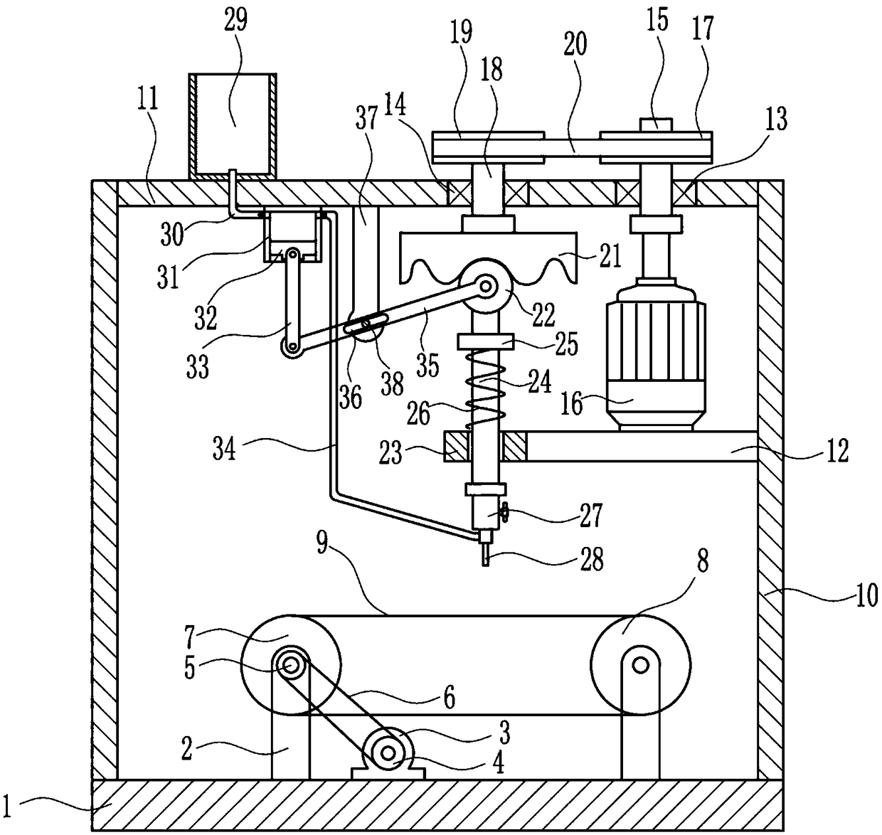
[0023] A kind of sole gluing device, such as Figure 1-5As shown, it includes base plate 1, pole 2, first motor 3, first pulley 4, second pulley 5, first flat belt 6, first large pulley 7, second large pulley 8, conveyor belt 9, the first A bracket 10, a horizontal plate 11, a first support plate 12, a first bearing seat 13, a second bearing seat 14, a first rotating shaft 15, a second motor 16, a third pulley 17, a second rotating shaft 18, and a fourth pulley 19 , the second flat belt 20, the cam 21, the contact wheel 22, the guide sleeve 23, the guide rod 24, the connection block 25, the spring 26, the rubber tube 27, the nozzle 28, the rubber bucket 29, the discharge pipe 30, the compression cylinder 31, Piston 32, first connecting rod 33, hose 34, second connecting rod 35, third connecting rod 37 and fourth rotating shaft 38, two struts 2 are arranged on the top of base plate 1, and the two struts 2 are separated by a certain distance, A first motor 3 is installed in the...

Embodiment 2

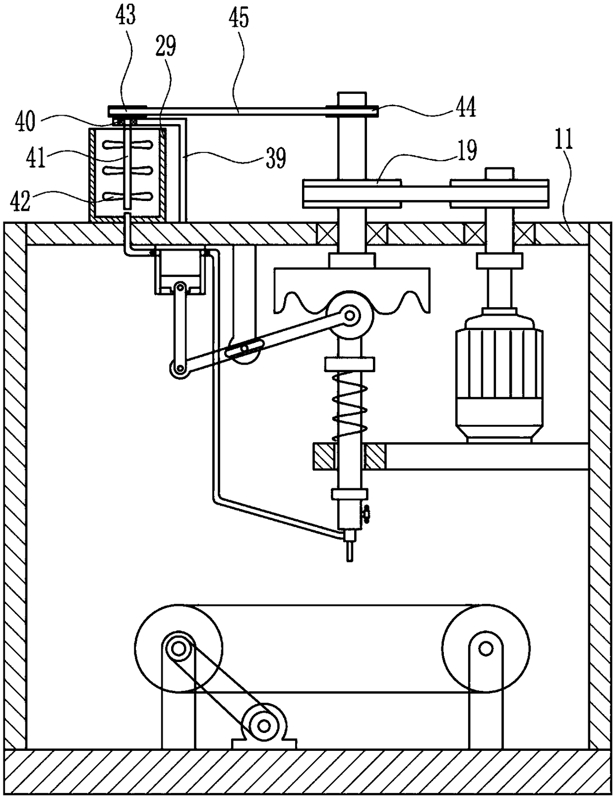
[0025] A kind of sole gluing device, such as Figure 1-5 As shown, it includes base plate 1, pole 2, first motor 3, first pulley 4, second pulley 5, first flat belt 6, first large pulley 7, second large pulley 8, conveyor belt 9, the first A bracket 10, a horizontal plate 11, a first support plate 12, a first bearing seat 13, a second bearing seat 14, a first rotating shaft 15, a second motor 16, a third pulley 17, a second rotating shaft 18, and a fourth pulley 19 , the second flat belt 20, the cam 21, the contact wheel 22, the guide sleeve 23, the guide rod 24, the connection block 25, the spring 26, the rubber tube 27, the nozzle 28, the rubber bucket 29, the discharge pipe 30, the compression cylinder 31, Piston 32, first connecting rod 33, hose 34, second connecting rod 35, third connecting rod 37 and fourth rotating shaft 38, two struts 2 are arranged on the top of base plate 1, and the two struts 2 are separated by a certain distance, A first motor 3 is installed in th...

Embodiment 3

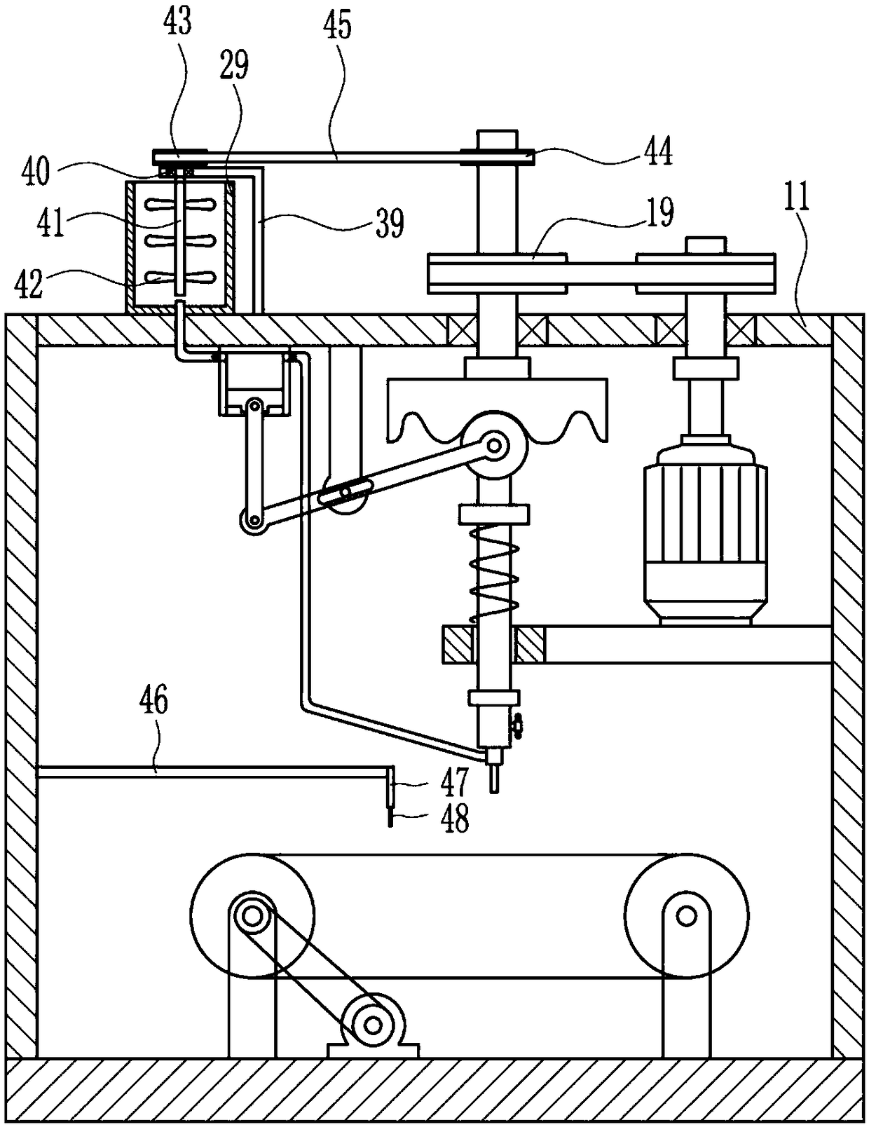
[0028] A kind of sole gluing device, such as Figure 1-5 As shown, it includes base plate 1, pole 2, first motor 3, first pulley 4, second pulley 5, first flat belt 6, first large pulley 7, second large pulley 8, conveyor belt 9, the first A bracket 10, a horizontal plate 11, a first support plate 12, a first bearing seat 13, a second bearing seat 14, a first rotating shaft 15, a second motor 16, a third pulley 17, a second rotating shaft 18, and a fourth pulley 19 , the second flat belt 20, the cam 21, the contact wheel 22, the guide sleeve 23, the guide rod 24, the connection block 25, the spring 26, the rubber tube 27, the nozzle 28, the rubber bucket 29, the discharge pipe 30, the compression cylinder 31, Piston 32, first connecting rod 33, hose 34, second connecting rod 35, third connecting rod 37 and fourth rotating shaft 38, two struts 2 are arranged on the top of base plate 1, and the two struts 2 are separated by a certain distance, A first motor 3 is installed in th...


PUM


Abstract

The invention relates to a gluing device, in particular to a shoe sole gluing device. The technical problem to be solved is how to provide a shoe sole gluing device which is high in efficiency and canprotect both hands. The technical scheme of the invention is that the shoe sole gluing device includes a base plate, supporting rods, a first motor, a first belt pulley, a second belt pulley, a firstflat belt and a first large belt pulley and the like. The top of the base plate is provided with the two supporting rods, the two supporting rods are arranged at a certain interval, the first motor is mounted at the middle of the top of the base plate, an output shaft of the first motor is connected with the first belt pulley through a coupling, the upper portion of the first bracket on the leftside is connected with the second belt pulley, and the first flat belt is connected between the second belt pulley and the first belt pulley. A conveying belt of the shoe sole gluing device drives shoes to move, and a piston moves up and down to drive glue to be sprayed out of a spray head, so that the glue is smeared on shoes, thereby improving gluing efficiency. Moreover, glue liquid on a shoe sole can be scraped more evenly through a soft scraping plate, and thus the glue is prevented from getting on your hands.

Description

technical field [0001] The invention relates to a gluing device, in particular to a shoe sole gluing device. Background technique [0002] Some shoes need to use glue between the sole and the body of the shoe to make it more tightly bonded, so the sole needs to be glued. At present, manual glue is generally used. Hold the shoes in one hand, and the glue in the other hand, and then apply the glue on the shoes. After such a long time of gluing, the arms will be sore, which will lead to low gluing efficiency, and it is easy to get the glue on the hands. In summer, the temperature is high. The glue applied on the shoes is easy to dry quickly, so it is not convenient to manually glue the soles, and the summer weather is relatively hot, so the mood of the workers is relatively turbulent. When the workers glue the soles, the workers tend to drop the glue on their hands. superior. Contents of the invention [0003] In order to overcome the disadvantages of low efficiency and eas...

Claims


Application Information

Patent Timeline
Patent Type & Authority Applications(China)
IPC IPC(8): A43D25/18
CPCA43D25/183
Inventor 张吉超
Owner NANJING LISHUI HIGH-TECH VENTURE CAPITAL MANAGEMENT CO LTD
Why Eureka
Try Eureka