Supercharge Your Innovation With Domain-Expert AI Agents!

Clamping fixture of displacement sensor

A displacement sensor and clamping tooling technology, applied in workpiece clamping devices, manufacturing tools, etc., can solve the problem of inconvenient adjustment of the displacement sensor, and achieve the effects of quick disassembly, reliable tooling, and improved measurement efficiency.

Inactive Publication Date: 2018-11-16
JIANGSU UNIV
View PDF8 Cites 2 Cited by
  • Summary
  • Abstract
  • Description
  • Claims
  • Application Information

AI Technical Summary

Problems solved by technology

[0003] In order to overcome the problems existing in the prior art proposed in the above-mentioned background technology, the patent of the present invention provides a displacement sensor clamping tool, which solves the problem that the displacement sensor is inconvenient to adjust during the actual test

Method used


Image

  • Clamping fixture of displacement sensor
  • Clamping fixture of displacement sensor
  • Clamping fixture of displacement sensor

Examples


Embodiment Construction

[0033] In order to further understand the present invention, the patent of the present invention will be further described in detail below in conjunction with the accompanying drawings, but it should not be understood that the scope of the above-mentioned subject of the patent of the present invention is limited to the above-mentioned embodiments.

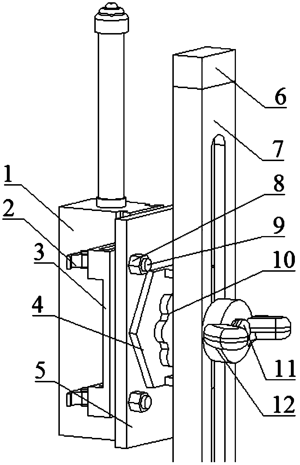
[0034] combined with figure 1 And attached Figure 5 , the displacement sensor 1 is an electronic component wrapped inside a metal casing, and there are slots on both sides of the metal casing, which are used to set the displacement sensor 1 in the U-shaped structure of the fixed block 3, and the cam wrench 2 and the rubber washer 15 are used to place the displacement sensor 1 The U-shaped structure is fixed and locked. When it is necessary to replace different sensors, the cam wrench 2 is loosened, and the metal shell is taken out from the U-shaped structure of the fixing block 3 .

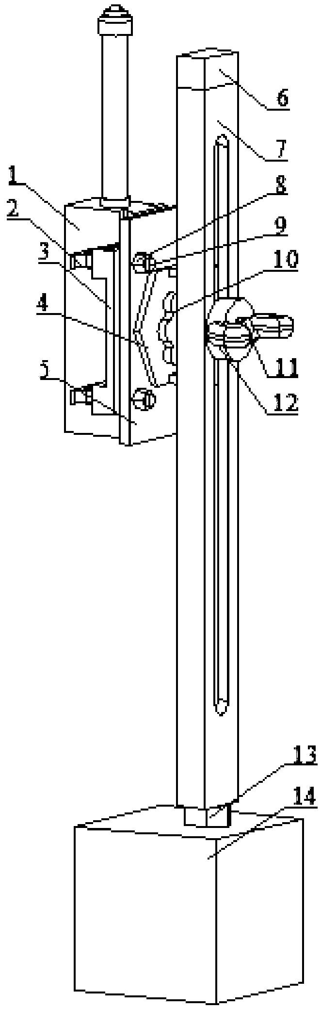
[0035] combined with figure 2 , 3 , 4 and ...


PUM


Abstract

The invention discloses a clamping fixture of a displacement sensor, and belongs to the technical field of sensor testing. The clamping fixture comprises a fixing component and a moving component, wherein the fixing component comprises a backing plate, fixing blocks, a threaded rod, a nut, a spline, a rubber gasket and cam wrenches; clamping slots are formed in the two sides of a sensor; the two fixing blocks are inserted into the clamping slots and are fixed to the backing plate in a locking manner through the cam wrenches; and the moving component comprises a first support, a threaded rod, aguide rail, a rotary knob and a base. The clamping fixture solves the problems that the prior art cannot adjust the position of the displacement sensor rapidly and conveniently. The clamping fixturecan realize continuous adjustment, is convenient to install, is convenient for replacing sensors of the same kind with different measuring ranges, is convenient to operate by testing personnel and canbe directly arranged on an existing sensor.

Description

technical field [0001] The invention belongs to the technical field of sensor testing, and in particular relates to a displacement sensor clamping tool. Background technique [0002] When measuring the stiffness of the car door and body, it is necessary to arrange some displacement sensors for the displacement of the loading point and the monitoring point. There is a variable resistor inside the displacement sensor. As the position of the ejector rod changes, the resistance value will change, so that the output voltage changes, the displacement can be obtained through conversion. Usually, the test engineer fixes the displacement sensor on the slender rod with iron sheets, iron wires, screws, etc., and then fixes the slender rod on the magnetic base, which is connected with the body-in-white test bench or other fixtures. However, when the monitoring point is changed, there are many problems such as inconvenient adjustment of the height and angle of the sensor, and unstable f...

Claims


Application Information

Patent Timeline
Patent Type & Authority Applications(China)
IPC IPC(8): B25B11/00
CPCB25B11/00
Inventor 汤霁骁朱茂桃姚鹏
Owner JIANGSU UNIV
Features
  • R&D
  • Intellectual Property
  • Life Sciences
  • Materials
  • Tech Scout
  • Unparalleled Data Quality
  • Higher Quality Content
  • 60% Fewer Hallucinations
Learn More