Pushing type wooden board cutting device for construction

A cutting device and push-type technology, applied in the direction of feeding devices, sawing components, sawing equipment, etc., to achieve the effect of preventing accidents

Inactive Publication Date: 2018-11-16
李子轩
View PDF7 Cites 20 Cited by
  • Summary
  • Abstract
  • Description
  • Claims
  • Application Information

AI Technical Summary

Problems solved by technology

[0003] In order to overcome the shortcomings of requiring the operator to manually push and press the wooden boards on the workbench for cutting, the technical problem to be solved: provide a push-type wooden board cutting device for construction that automatically pushes the wooden boards and cuts without pressing the wooden boards by hand

Method used


Image

  • Pushing type wooden board cutting device for construction
  • Pushing type wooden board cutting device for construction
  • Pushing type wooden board cutting device for construction

Examples


Embodiment 1

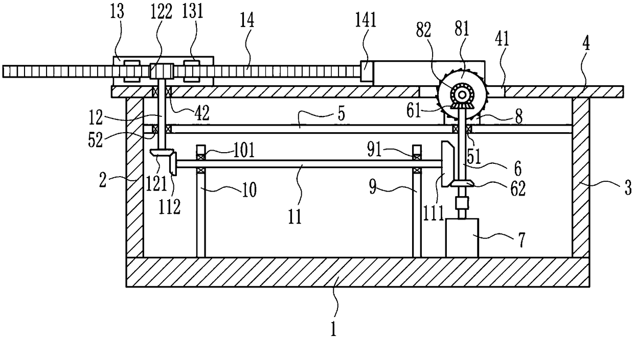
[0017] A push-type plank cutting device for construction, such as Figure 1-3 As shown, it includes a base 1, a first support 2, a second support 3, a workbench 4, a first bearing 42, a third support 5, a second bearing 51, a third bearing 52, a first shaft 6, a first Bevel gear 61, second bevel gear 62, motor 7, mounting plate 8, cutting piece 81, third bevel gear 82, fourth bracket 9, fourth bearing 91, fifth bracket 10, fifth bearing 101, second shaft Rod 11, fourth bevel gear 111, fifth bevel gear 112, third shaft rod 12, sixth bevel gear 121, spur gear 122, slide rail 13, slider 131, rack 14 and push plate 141, above base 1 The left side is fixedly connected with the first bracket 2, the right side above the base 1 is fixedly connected with the second bracket 3, the top of the first bracket 2 and the second bracket 3 are fixedly connected with the workbench 4, and the left side of the workbench 4 is provided with a first slot Hole 41, a first bearing 42 is embedded on th...

Embodiment 2

[0019] A push-type plank cutting device for construction, such as Figure 1-3As shown, it includes a base 1, a first support 2, a second support 3, a workbench 4, a first bearing 42, a third support 5, a second bearing 51, a third bearing 52, a first shaft 6, a first Bevel gear 61, second bevel gear 62, motor 7, mounting plate 8, cutting piece 81, third bevel gear 82, fourth bracket 9, fourth bearing 91, fifth bracket 10, fifth bearing 101, second shaft Rod 11, fourth bevel gear 111, fifth bevel gear 112, third shaft rod 12, sixth bevel gear 121, spur gear 122, slide rail 13, slider 131, rack 14 and push plate 141, above base 1 The left side is fixedly connected with the first bracket 2, the right side above the base 1 is fixedly connected with the second bracket 3, the top of the first bracket 2 and the second bracket 3 are fixedly connected with the workbench 4, and the left side of the workbench 4 is provided with a first slot Hole 41, a first bearing 42 is embedded on the...

Embodiment 3

[0022] A push-type plank cutting device for construction, such as Figure 1-3 As shown, it includes a base 1, a first support 2, a second support 3, a workbench 4, a first bearing 42, a third support 5, a second bearing 51, a third bearing 52, a first shaft 6, a first Bevel gear 61, second bevel gear 62, motor 7, mounting plate 8, cutting piece 81, third bevel gear 82, fourth bracket 9, fourth bearing 91, fifth bracket 10, fifth bearing 101, second shaft Rod 11, fourth bevel gear 111, fifth bevel gear 112, third shaft rod 12, sixth bevel gear 121, spur gear 122, slide rail 13, slider 131, rack 14 and push plate 141, above base 1 The left side is fixedly connected with the first bracket 2, the right side above the base 1 is fixedly connected with the second bracket 3, the top of the first bracket 2 and the second bracket 3 are fixedly connected with the workbench 4, and the left side of the workbench 4 is provided with a first slot Hole 41, a first bearing 42 is embedded on th...


PUM


Abstract

The invention relates to a cutting device, in particular to a pushing type wooden board cutting device for construction. The pushing type wooden board cutting device aims at achieving the effects of pushing a wooden board automatically and conducting cutting without hand pressing. The pushing type wooden board cutting device comprises a base, a first bracket, a second bracket, a worktable, a first bearing, a third bracket, a second bearing and a third bearing. The first bracket is fixedly connected to the left side above the base, and the second bracket is fixedly connected to the right sideabove the base. The top ends of the first bracket and the second bracket are fixedly connected with the worktable, and a first slot is formed in the left side of the worktable. The cutting device hasthe function of cutting the wooden board, solves the problem of danger caused by manual pushing of the wooden board for cutting, and further achieves the function of pressing the wooden board for fixing to ensure the safety of an operator. A fixed block and a handle are arranged. When a first fixed plate moves up, the first fixing plate can be prevented from dropping and clamping the hands of theoperator.

Description

technical field [0001] The invention relates to a cutting device, in particular to a push type wood board cutting device for construction. Background technique [0002] When the construction site needs to cut wooden boards for construction, most of the cutting devices require the operator to manually push the wooden boards on the workbench for cutting. When pushing the wooden boards, the operator needs to press the wooden boards with his hands to prevent the wooden boards from shifting during the cutting process. , After pressing and pushing the wooden board for a long time to cut, it will make people feel tired, and the operator often cuts the hand. In this way, after cutting the wooden board for a period of time, the operator needs to rest for a period of time, so it cannot be satisfied Demand for planks on construction sites. Contents of the invention [0003] In order to overcome the shortcoming that the operator needs to manually push and press the wood board on the ...

Claims


Application Information

Patent Timeline
Patent Type & Authority Applications(China)
IPC IPC(8): B27B5/22B27B5/29B27B25/00B27B29/00
CPCB27B5/222B27B5/29B27B25/00B27B29/00
Inventor 李子轩
Owner 李子轩
Why Eureka
Try Eureka