Chip cutting and cleaning equipment

A technology for cleaning equipment and chips, applied in stone processing equipment, work accessories, fine work devices, etc., can solve the problems of difficulty in cleaning debris, high purchase cost of CNC machine tools, and low cleaning efficiency of debris, etc. Low purchase cost and good cleaning effect

Inactive Publication Date: 2018-11-16
重庆市嘉凌新科技有限公司
View PDF13 Cites 0 Cited by
  • Summary
  • Abstract
  • Description
  • Claims
  • Application Information

AI Technical Summary

Problems solved by technology

[0003] In the prior art, during the dicing process of the wafer, the debris generated by the wafer cutting needs to be cleaned. However, since the particles of the debris are relatively small, they are easy to adhere to the cutting groove on the wafer, so the debr

Method used


Image

  • Chip cutting and cleaning equipment
  • Chip cutting and cleaning equipment
  • Chip cutting and cleaning equipment

Examples


Embodiment Construction

[0016] The following is further described in detail through specific implementation methods:

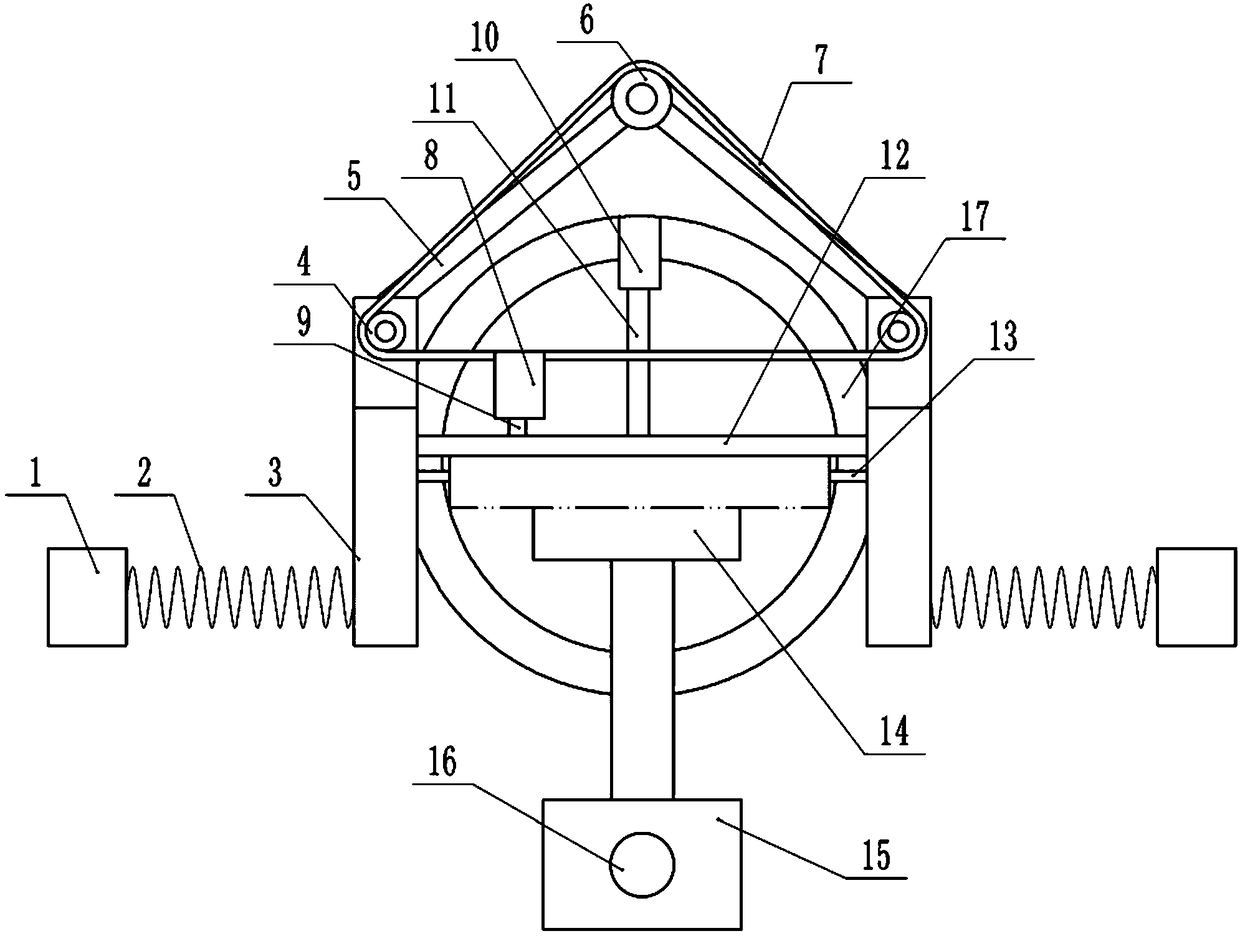
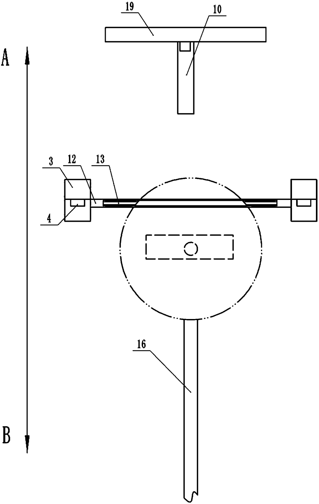
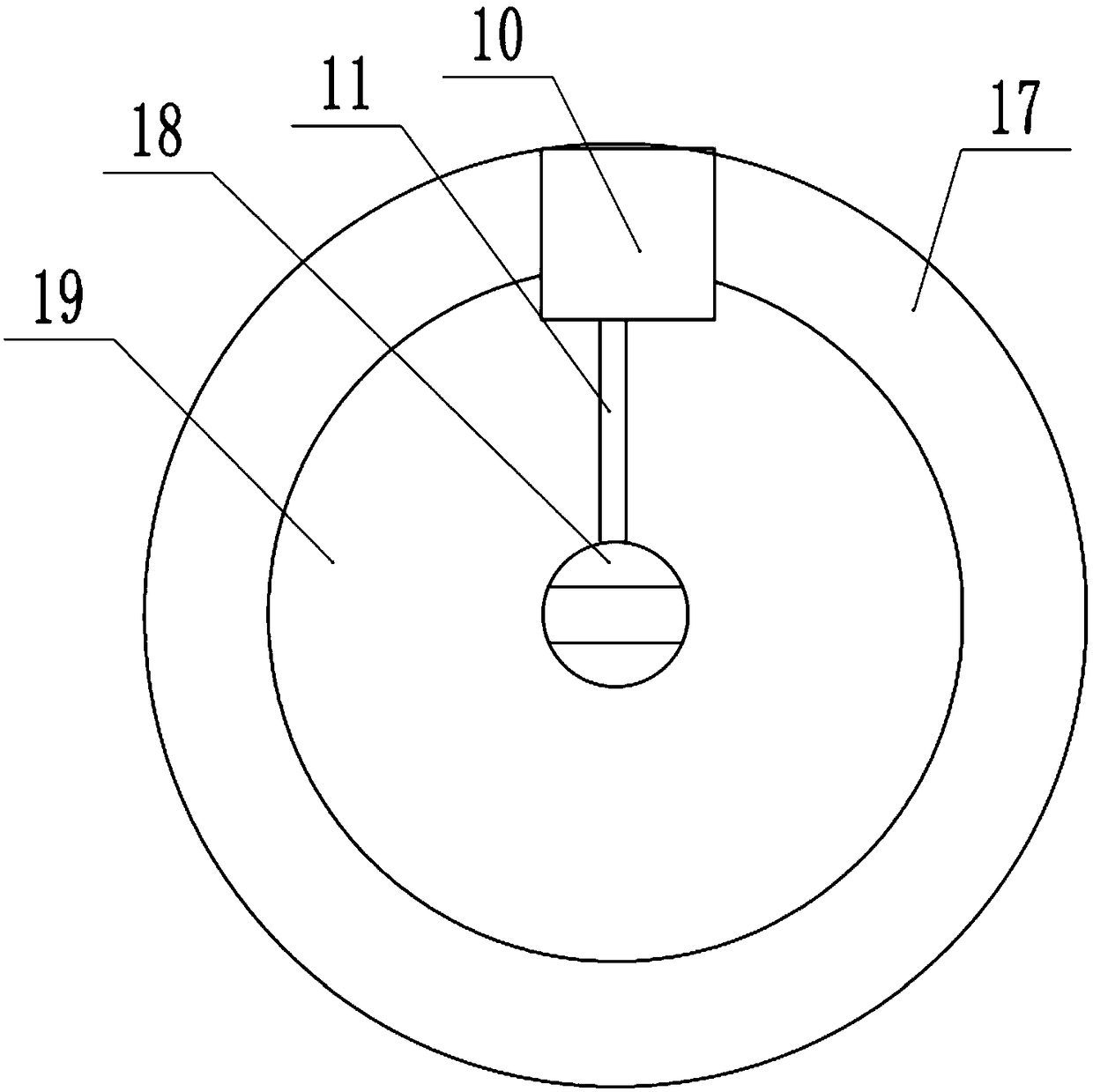
[0017] The reference signs in the drawings of the description include: pressing block 1, pressing spring 2, detection block 3, first sprocket 4, swing lever 5, second sprocket 6, chain 7, cutting machine 8, cutting knife 9, nozzle 10. Connecting rod 11, pressing plate 12, detection rod 13, suction cup 14, moving block 15, lead screw 16, chute 17, clip 18, cleaning plate 19.

[0018] The embodiment is basically as attached Figure 1-Figure 3 Shown: Chip cutting and cleaning equipment, including a frame, which is equipped with a cutting mechanism, a cleaning mechanism and a moving mechanism, combined with figure 1 and figure 2 As shown, A in this embodiment refers to the rear of the car, and B refers to the front of the car. The cleaning mechanism is located at the rear of the cutting mechanism, and the moving mechanism is located below the cutting mechanism.

[0019] combine Fi...


PUM


Abstract

The invention relates to the field of chip processing, in particular to chip cutting and cleaning equipment. The chip cutting and cleaning equipment comprises a cutting mechanism and a cleaning mechanism. The cleaning mechanism comprises a vertically-arranged cleaning disc. The middle of the cleaning disc is rotationally connected with a clamp used for clamping a wafer. The cleaning disc is provided with an annular sliding groove. The clamp is located at the circle center of the sliding groove. The sliding groove is slidably connected with a spraying head. A connecting rod is connected betweenthe clamp and the spraying head. The clamp is connected with a first motor used for driving the clamp to rotate. According to the chip cutting and cleaning equipment, the cleaning efficiency of the wafer in the cutting process is improved.

Description

technical field [0001] The invention relates to the field of chip processing, in particular to chip cutting and cleaning equipment. Background technique [0002] Wafer refers to the silicon wafer used in the production of silicon semiconductor integrated circuits. Because of its circular shape, it is called a wafer. During the processing of the wafer, the surface of the wafer needs to be cut, so as to cut the surface of the wafer into several individual chips, and during the cutting process, the surface of the wafer forms cutting grooves. [0003] In the prior art, during the dicing process of the wafer, the debris generated by the wafer cutting needs to be cleaned. However, since the particles of the debris are relatively small, they are easy to adhere to the cutting groove on the wafer, so the debris of the debris is relatively small. It is difficult to clean up, and the cleaning efficiency of debris is low. Moreover, most of the current wafer cutting devices are CNC mac...

Claims


Application Information

Patent Timeline
IPC IPC(8): B28D5/04B28D7/02B28D7/00B28D7/04
CPCB28D5/0058B28D5/0076B28D5/0094B28D5/04
Inventor 黄晓波
Owner 重庆市嘉凌新科技有限公司
Why Eureka
Try Eureka