Unrolling machine capable of conducting continuous roll supply and automatic unrolling

A technology of an unwinder and an unwinder mechanism, which is applied in the field of machinery, can solve the problems that the quality of the laying surface cannot be effectively controlled, the speed setting that cannot be laid, and the labor cost is large, so as to improve the laying efficiency and reduce labor costs. Cost, the effect of saving labor costs

Inactive Publication Date: 2018-11-16
王红燕
View PDF0 Cites 8 Cited by
  • Summary
  • Abstract
  • Description
  • Claims
  • Application Information

AI Technical Summary

Problems solved by technology

[0003] 1. Because the glass fiber cloth roll is large and heavy, multiple people are required to pull the cloth when unwinding, and it needs to be laid with the help of the top crane. The whole laying process is long, labor-intensive, and inefficient;
[0004] 2. When laying by manual pulling, the speed of laying cannot be specifically set, so that the quality of the laying surface cannot be effectively controlled;
[0005] 3. The glass fiber cloth rolls on the frame are arranged in multiple layers. When the cloth rolls are used up, the new cloth rolls need to be hoisted to the frame by means of a crane, and it needs the assistance of multiple people to complete the operation, which consumes a lot of labor costs. , takes a long time

Method used


Image

  • Unrolling machine capable of conducting continuous roll supply and automatic unrolling
  • Unrolling machine capable of conducting continuous roll supply and automatic unrolling
  • Unrolling machine capable of conducting continuous roll supply and automatic unrolling

Examples


Embodiment Construction

[0026] The following will clearly and completely describe the technical solutions in the embodiments of the present invention with reference to the accompanying drawings in the embodiments of the present invention. Obviously, the described embodiments are only some, not all, embodiments of the present invention. Based on the embodiments of the present invention, all other embodiments obtained by persons of ordinary skill in the art without making creative efforts belong to the protection scope of the present invention.

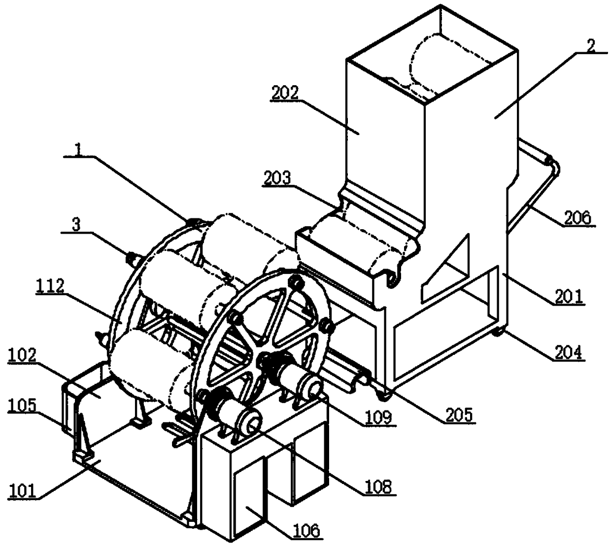
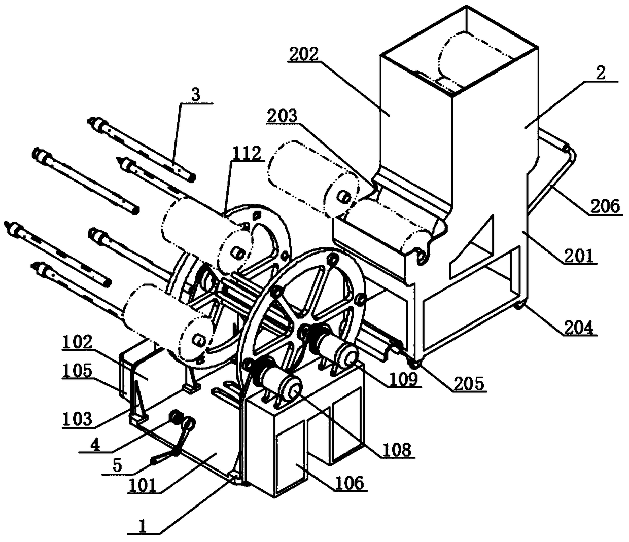
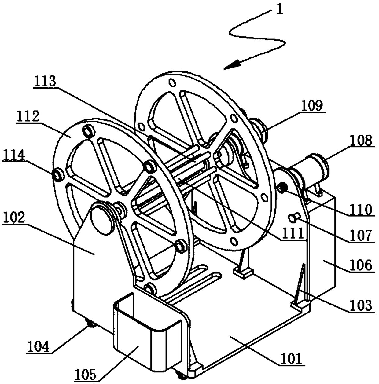
[0027] see Figure 1-7 , the present invention provides a technical solution: an unwinding machine with continuous roll supply and automatic unwinding, comprising an unwinding mechanism 1 and a roll supplying mechanism 2 set at the rear end of the unwinding mechanism 1, and the unwinding mechanism 1 The main body is a frame structure, and a plate-shaped support base 101 is provided at the lower end of the unwinding mechanism 1, and side support plates 102 of a...


PUM


Abstract

The invention discloses an unrolling machine capable of conducting continuous roll supply and automatic unrolling. The unrolling machine comprises an unrolling mechanism and a roll supply mechanism arranged at the rear end of the unrolling mechanism. A body of the unrolling mechanism is of a frame structure. The lower end of the unrolling mechanism is provided with a supporting bottom plate of a platy structure. The left side and the right side of the supporting bottom plate are provided with side supporting plates which are perpendicular to the supporting bottom plate and are of a platy structure. A main shaft of a cylindrical structure is connected between the two side supporting plates in a matched manner. The parts, between the two side supporting plates, of the two ends of the main shaft are sleeved with rotary discs of a disc-shaped structure in a matched manner. A main shaft of an unrolling motor is driven to drive a roll shaft engaged with a linkage wheel to rotate together, accordingly, the automatic unrolling action of a glass fiber cloth roll sleeving the roll shaft outer circle is conducted, the manpower cost is saved, and the pavement efficiency is improved; and the unrolling rotation speed can be set by adjusting the rotation speed of the unrolling motor, accordingly the pavement speed is more reasonable, and the pavement face quality is greatly improved.

Description

technical field [0001] The invention relates to the technical field of machinery, in particular to an unwinding machine capable of continuous roll supply and automatic roll unwinding. Background technique [0002] During the production process of fan blades, it is necessary to lay multiple layers of glass fiber cloth on the surface of the mold, but in the laying process, it is necessary to set up an unwinding frame, and set the cloth rolls on the unwinding frame for use. This type of unwinding frame The structure is relatively simple, and the production is relatively easy, but it still has the following disadvantages in actual use: [0003] 1. Because the glass fiber cloth roll is large and heavy, multiple people are required to pull the cloth when unwinding, and it needs to be laid with the help of the top crane. The whole laying process is long, labor-intensive, and inefficient; [0004] 2. When laying by manual pulling, the speed of laying cannot be specifically set, so ...

Claims


Application Information

Patent Timeline
Patent Type & Authority Applications(China)
IPC IPC(8): B65H16/06B65H16/10B65H19/12B65H43/00
CPCB65H16/06B65H16/10B65H19/126B65H43/00B65H2701/1133B65H2701/174
Inventor 王红燕陈凯黄培康
Owner 王红燕
Why Eureka
Try Eureka