
Rotary compressor, gas compression system, refrigeration system and heat pump system

A technology of rotary compressors and cylinders, which is applied in the field of compressor manufacturing, can solve the problems of needle rolling stuck failure, compressor stuck failure, contact stress increase, etc., to reduce friction power consumption, improve stress, reduce The effect of friction loss

Active Publication Date: 2018-11-16
GUANGDONG MEIZHI PRECISION MFG
View PDF5 Cites 5 Cited by
  • Summary
  • Abstract
  • Description
  • Claims
  • Application Information

AI Technical Summary

Problems solved by technology

However, the needle roller structure has extremely high requirements on reliability. Due to the sharp increase of the contact stress between the needle roller and the piston, it poses a challenge to the wear resistance of the needle roller material, and the needle roller structure is prone to needle roller jamming failure. Once the needle roller fails, the needle roller will wear out sharply until the compressor is stuck and fails, so there is room for improvement

Method used


Image

  • Rotary compressor, gas compression system, refrigeration system and heat pump system
  • Rotary compressor, gas compression system, refrigeration system and heat pump system
  • Rotary compressor, gas compression system, refrigeration system and heat pump system

Examples


Embodiment 1

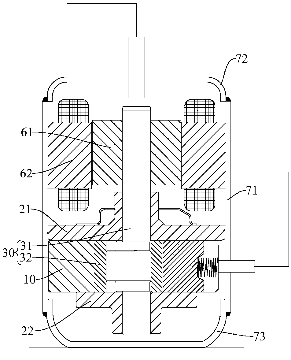
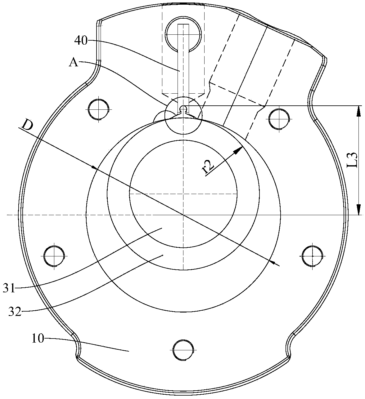
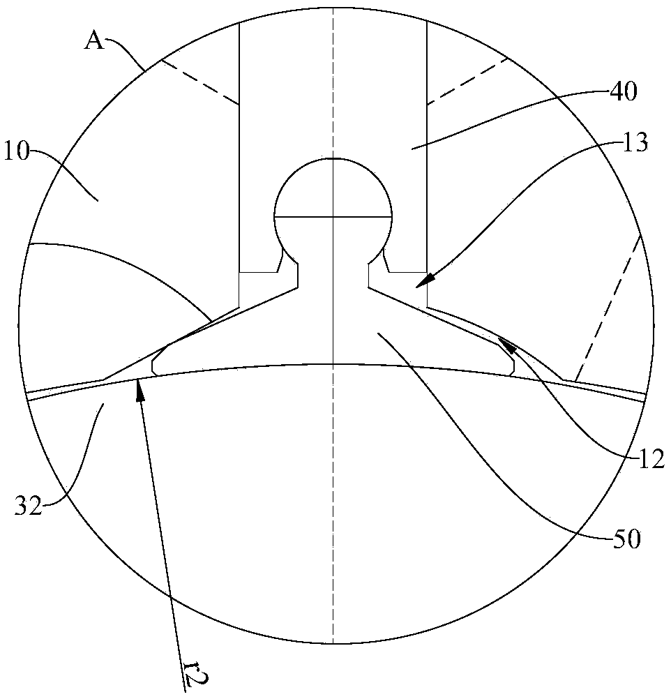
[0044] Refer below Figure 1-Figure 35 A rotary compressor according to an embodiment of the present invention is described. The rotary compressor includes: a casing, a stator 62 , a rotor 61 , a cam mechanism 30 , a cylinder 10 , a main bearing 21 , an auxiliary bearing 22 , a sliding vane 40 and a rocker 50 .

[0045] Among them, refer to figure 1 , the casing can include a casing body 71, an upper casing 72, a lower casing 73, and the stator 62, the rotor 61, the cam mechanism 30, the cylinder 10, the main bearing 21, the auxiliary bearing 22, the sliding plate 40 and the rocker 50 can be installed in the inside the case.

[0046] The rotor 61 is connected with the cam mechanism 30 to drive the cam mechanism 30 to rotate. The main bearing 21 and the auxiliary bearing 22 are respectively arranged on the upper and lower surfaces of the cylinder 10, and a compression chamber is defined between the cylinder 10, the main bearing 21 and the auxiliary bearing 22. , the cam porti...

Embodiment 2

[0054] Refer below Figure 1-Figure 35 A rotary compressor according to an embodiment of the present invention is described. The rotary compressor includes: a casing, a stator 62 , a rotor 61 , a cam mechanism 30 , a cylinder 10 , a main bearing 21 , an auxiliary bearing 22 , a sliding vane 40 and a rocker 50 .

[0055] Among them, refer to figure 1 , the casing can include a casing body 71, an upper casing 72, a lower casing 73, and the stator 62, the rotor 61, the cam mechanism 30, the cylinder 10, the main bearing 21, the auxiliary bearing 22, the sliding plate 40 and the rocker 50 can be installed in the inside the case.

[0056] The rotor 61 is connected with the cam mechanism 30 to drive the cam mechanism 30 to rotate. The main bearing 21 and the auxiliary bearing 22 are respectively arranged on the upper and lower surfaces of the cylinder 10, and a compression chamber is defined between the cylinder 10, the main bearing 21 and the auxiliary bearing 22. , the cam porti...

Embodiment 3

[0067] Refer below Figure 1-Figure 4 , Image 6 , Figure 8-Figure 10 , Figure 12 , Figure 14-Figure 35 A rotary compressor according to an embodiment of the present invention is described. The rotary compressor includes: a casing, a stator 62 , a rotor 61 , a cam mechanism 30 , a cylinder 10 , a main bearing 21 , an auxiliary bearing 22 , a sliding plate 40 and a rocker 50 .

[0068] Among them, refer to figure 1 , the casing can include a casing body 71, an upper casing 72, a lower casing 73, and the stator 62, the rotor 61, the cam mechanism 30, the cylinder 10, the main bearing 21, the auxiliary bearing 22, the sliding plate 40 and the rocker 50 can be installed in the inside the case.

[0069] The rotor 61 is connected with the cam mechanism 30 to drive the cam mechanism 30 to rotate. The main bearing 21 and the auxiliary bearing 22 are respectively arranged on the upper and lower surfaces of the cylinder 10, and a compression chamber is defined between the cylind...


PUM


Abstract

The invention discloses a rotary compressor, a gas compression system, a refrigeration system and a heat pump system. The rotary compressor comprises an air cylinder, a crankshaft, a piston, a main bearing, an auxiliary bearing, a sliding piece and a rocking block, wherein the piston sleeves the eccentric part of a crankshaft, and the piston is rotatably arranged in an air cylinder; a clamping structure which is used for limiting circumferential direction movement generated between the crankshaft and the piston is arranged between the eccentric part of the crankshaft and the piston, and a sliding piece groove is formed in the air cylinder, the sliding piece is installed in the sliding piece groove, the rocking block and the tip end of the sliding piece wind around a first axis in a hingedmode, the first axis is parallel to the axis of the air cylinder, and the rocking block is abutted against the outer circle face of the piston in a pressed mode. According to the rotary compressor, the lubricating state between the sliding piece and the friction pair of a cam part is improved, the friction power consumption between the friction pair of the cam part and the sliding piece is greatlyreduced, and friction loss between the eccentric part of the crankshaft and the piston can be effectively reduced.

Description

technical field [0001] The invention belongs to the technical field of compressor manufacturing, and in particular relates to a rotary compressor, a gas compression system with the rotary compressor, a refrigeration system with the rotary compressor and a heat pump with the rotary compressor system. Background technique [0002] In the compressor mechanism, the friction loss between the tip of the slide plate and the outer surface of the piston is relatively large. In order to reduce this friction loss, in the related art, a needle roller is installed at the tip of the sliding plate. The purpose of this structure is to change the sliding friction between the piston and the sliding plate into rolling friction, and the friction power consumption is effectively reduced. However, the needle roller structure has extremely high requirements on reliability. Due to the sharp increase of the contact stress between the needle roller and the piston, it poses a challenge to the wear re...

Claims


Application Information

Patent Timeline
Patent Type & Authority Applications(China)
IPC IPC(8): F04C18/356F04C29/00F04C29/02
CPCF04C18/3564F04C29/00F04C29/02
Inventor 蒋君之李盖敏朱运农李华明陈中贵
Owner GUANGDONG MEIZHI PRECISION MFG
Learn More