Supercharge Your Innovation With Domain-Expert AI Agents!

Automatic releasing device of accumulated water for vacuum pump oil tank

An automatic release and vacuum pump technology, applied in the direction of valve operation/release device, valve device, pumping device for elastic fluid, etc., can solve the problem of damage to the lubrication performance of the pump head, failure of the vacuum pump, pump body and Rotor rust and other problems, to avoid adverse effects, prolong service life, ensure the effect of lubricating performance

Pending Publication Date: 2018-11-16
苏州沧海真空机械有限公司
View PDF0 Cites 2 Cited by
  • Summary
  • Abstract
  • Description
  • Claims
  • Application Information

AI Technical Summary

Problems solved by technology

[0003] The disadvantage of the above structure is: once the vacuum pump handles the water vapor that exceeds the design capacity, the water will condense into liquid, and remain at the bottom of the oil tank body 1 after a period of time
like figure 2 As shown, when the accumulated water 3 remains in the lower part of the cavity of the oil tank body 1, the lubricating oil 2 will float due to the low density. As long as the oil-water interface 31 reaches the height of the oil return hole 11, the accumulated water 3 will replace the lubricating oil. The oil 2 is pumped back to the pump head to participate in the lubrication work, thereby destroying the lubrication performance of the pump head, resulting in serious consequences such as rusting of the pump body and rotor, and cracking of the blades
If the lubricating oil 2 is not replaced in time, the vacuum pump will fail soon

Method used


Image

  • Automatic releasing device of accumulated water for vacuum pump oil tank
  • Automatic releasing device of accumulated water for vacuum pump oil tank
  • Automatic releasing device of accumulated water for vacuum pump oil tank

Examples


Embodiment Construction

[0017] The applicant will describe in detail below in the form of the embodiment, but the description of the embodiment is not a limitation to the solution of the present invention, and any equivalent transformation made according to the concept of the present invention is only in form and not in substance. It should be regarded as the scope of the technical solution of the present invention.

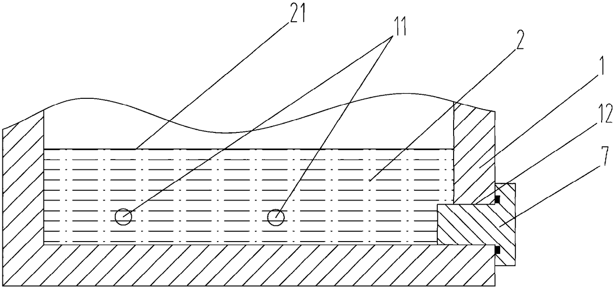
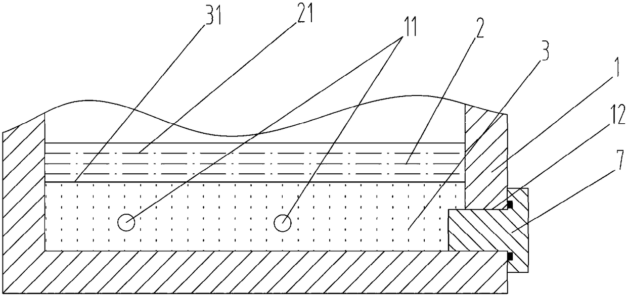
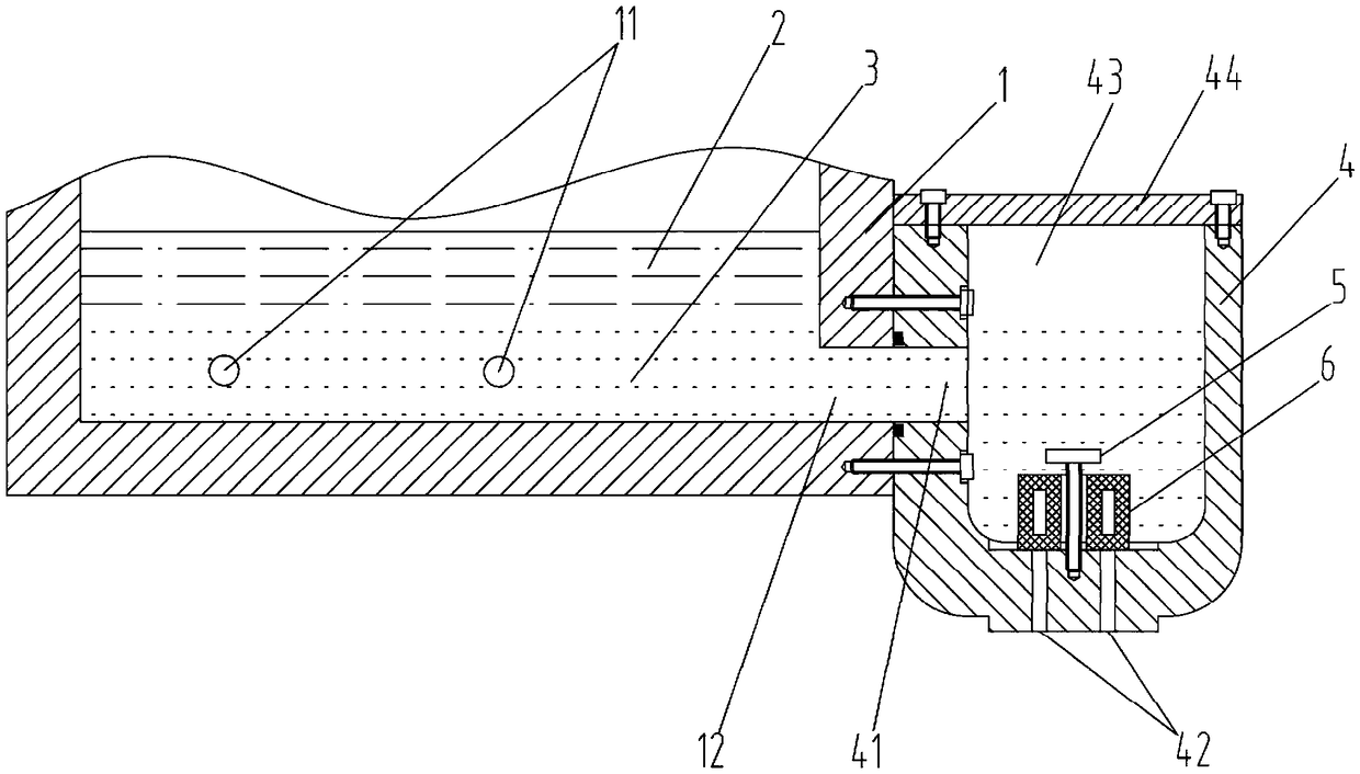
[0018] see figure 1 , the present invention relates to an automatic release device for accumulated water in a vacuum pump oil tank. The vacuum pump oil tank includes an oil tank body 1, and a lubricating oil 2 is arranged in a hollow cavity of the oil tank body 1. Below the lubricating oil 2 is accumulated water 3. An oil return hole 11 and an oil discharge hole 12 are opened on the oil tank body 1 . The feature is: the automatic water release device includes an additional cavity 4, which is arranged beside the fuel tank body 1 and on one side of the oil discharge hole 12, and the addi...


PUM


Abstract

The invention discloses an automatic releasing device of accumulated water for a vacuum pump oil tank. The vacuum pump oil tank comprises an oil tank body, lubricating oil is arranged in a cavity of the oil tank body, the accumulated water is located below the lubricating oil, oil return holes and an oil drain hole are formed in the oil tank body, the releasing device is characterized by comprising an additional cavity, the additional cavity is arranged beside the oil tank body and located on one side of the oil drain hole, an oil inlet is formed in one side wall body of the additional cavity,the oil inlet communicates with the oil drain hole, a water storage cavity is formed in the middle of the additional cavity, water discharging holes are formed in the bottom of the additional cavity,a floater is arranged in the water storage cavity and is limited at the bottom of the additional cavity through a positioning screw and can float up and down, when no accumulated water exists in thewater storage cavity, the floater is used for sealing the water discharging holes, when water is accumulated at the lower part of the water storage cavity, the floater can float upwards to open the water discharging holes, the accumulated water is discharged out of the water storage cavity, then the density of liquid in contact with the floater is reduced along with descending of the water level,and the floater gradually descends and seals the water discharging holes. According to the automatic releasing device of the accumulated water for the vacuum pump oil tank, the adverse effect on the vacuum pump by the moisture is avoided, the lubricating performance of a pump head is ensured, and the cost is saved.

Description

technical field [0001] The invention belongs to the technical field of vacuum pumps, in particular to an automatic water release device for a vacuum pump oil tank. Background technique [0002] The oil-lubricated rotary vane vacuum pump is one of the most basic vacuum obtaining equipment in vacuum technology. The typical structure of its oil tank is composed of figure 1 As disclosed, it includes a fuel tank body 1, lubricating oil 2 is arranged in the hollow cavity of the fuel tank body 1, an oil return hole 11 and an oil discharge hole 12 are opened on the fuel tank body 1, and a discharge hole 12 is arranged in the oil discharge hole 12. The oil bolt or valve 7, the lubricating oil 2 returns to the pump head through the oil return hole 11 to continue to participate in the work, and the discharged oil gas returns to the surface of the lubricating oil level 21, so that the lubricating oil level 21 reaches a dynamic balance. When needing to repair or maintain, open oil drain...

Claims


Application Information

Patent Timeline
IPC IPC(8): F16K31/18F16N19/00F04C29/02
CPCF04C29/02F16K31/18F16N19/00
Inventor 高峰
Owner 苏州沧海真空机械有限公司
Features
  • R&D
  • Intellectual Property
  • Life Sciences
  • Materials
  • Tech Scout
  • Unparalleled Data Quality
  • Higher Quality Content
  • 60% Fewer Hallucinations
Learn More