Air conditioner external unit

An air-conditioning outdoor unit and host technology, applied in air-conditioning systems, space heating and ventilation, household heating and other directions, can solve the problems of indoor temperature increase, reduction of the service life of the internal host, increase of the temperature of the outer wall, etc., to reduce the overall temperature , the effect of reducing the temperature rise of the external wall

Inactive Publication Date: 2018-11-16
陆茹姣
View PDF4 Cites 1 Cited by
  • Summary
  • Abstract
  • Description
  • Claims
  • Application Information

AI Technical Summary

Problems solved by technology

[0002] The air conditioner external unit is generally installed on the external wall of the building. In order to dissipate heat for the internal refrigeration unit, the air conditioner external unit generally installs a heat dissipation component on the outer side of the air conditioner external unit. The heat dissipation component generally uses an impeller, through which the heat dissipation component Air inhalation blows the outside airflow into the air conditioner external unit to realize heat dissipation. At the same time, the back of the air conditioner external unit will release heat, that is, the side opposite to the building body. The heat will have a certain impact on the building body, especially the installation For a building with a metal curtain wall, the heat generated by the external unit will heat up the metal curtain wall, causing the temperature of the outer wall of the entire building to rise, which in turn leads to an increase in the indoor temperature
Moreover, the general way of air intake and air intake can only achieve natural air cooling, and the heat dissipation effect is poor. The air conditioner may not be able to cool normally due to overheating, and the service life of the internal host will be reduced.

Method used


Image

  • Air conditioner external unit
  • Air conditioner external unit
  • Air conditioner external unit

Examples


Embodiment Construction

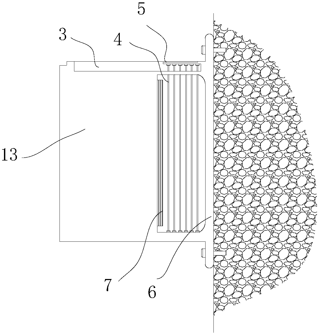
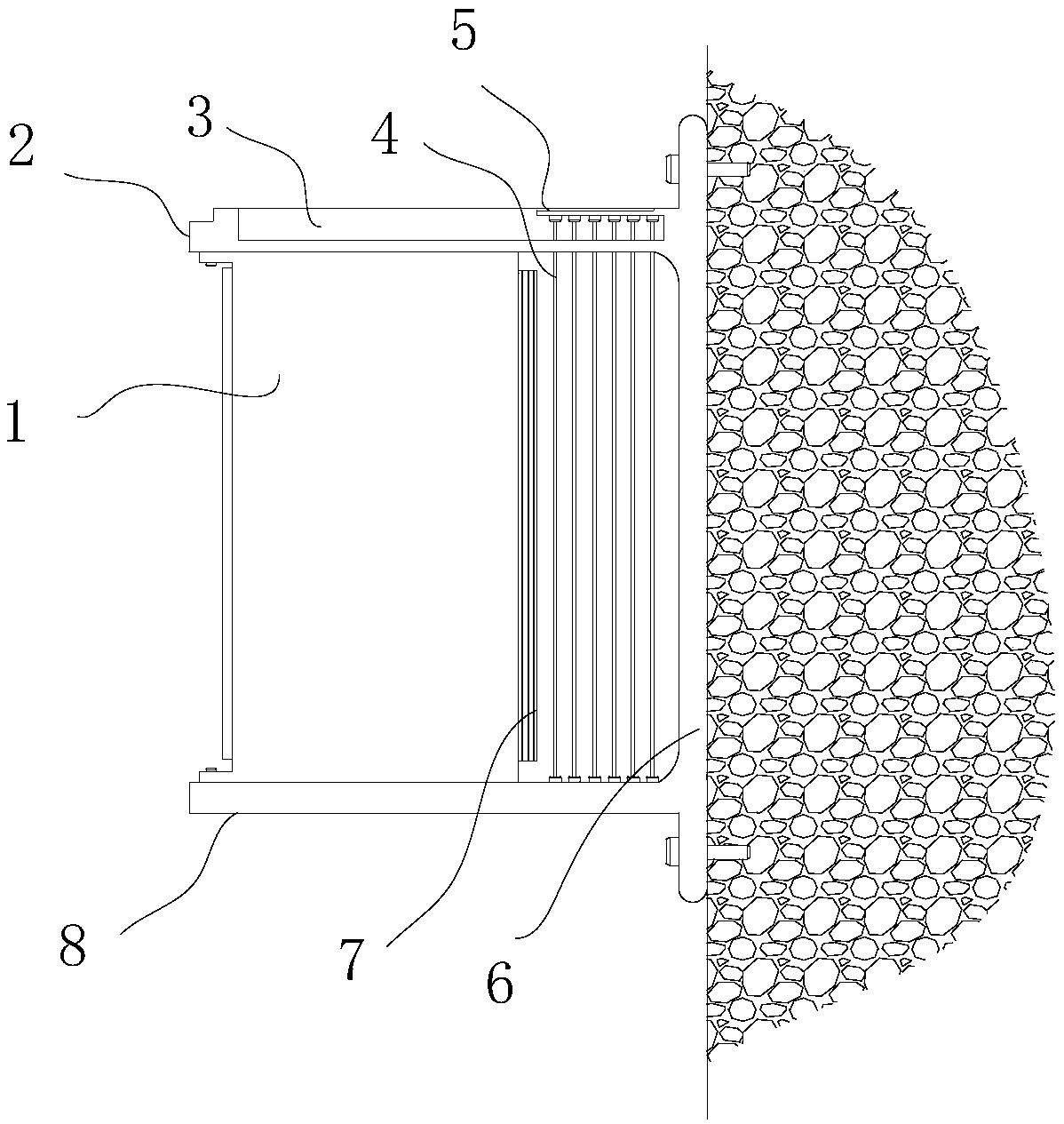
[0017] Such as figure 1 with figure 2 As shown, the air conditioner external unit includes an external unit housing 6, and an external unit main unit 1 installed in the external unit housing 6, and an installation cavity 12 for installing the external unit main unit is provided in the middle of the external unit housing 6. , the external machine host 1 is fixedly installed on the bottom surface of the installation cavity 12 through the connecting feet and screws at the bottom. The both sides of the bottom surface of 12 respectively offer an air inlet chamber 11, and in the air inlet chamber 11, dislocation is provided with more than one water-absorbing line 4, and water-absorbing line 4 is covered with straightening after absorbing water and is arranged on the air inlet place of air inlet chamber 11.

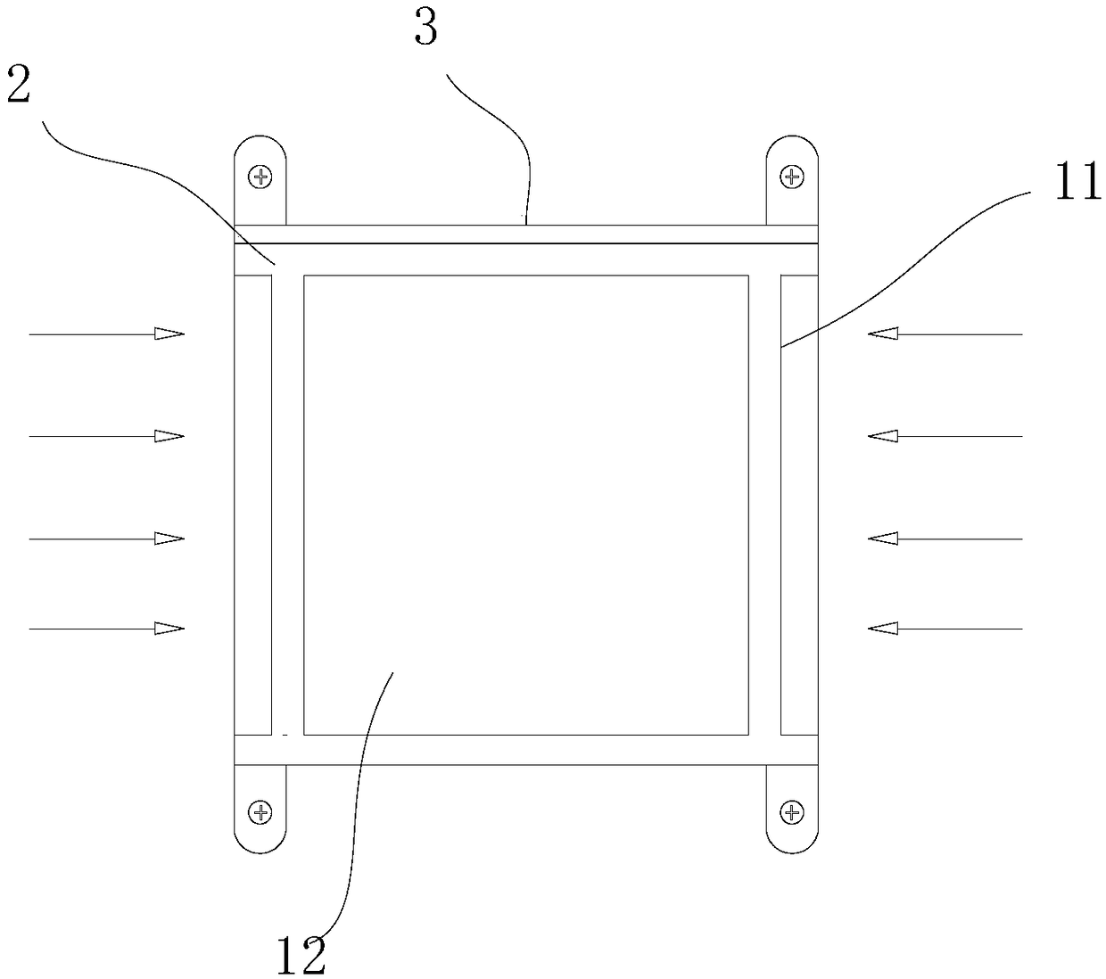
[0018] Such as image 3 As shown, a top plate 2 is arranged on the top of the outer machine casing 6, a bottom plate 8 is arranged on the bottom, and side plates 13 are arran...


PUM


Abstract

The invention discloses an air conditioner external unit which comprises an external unit housing and an external unit main machine installed in the external unit housing. The middle of the external unit housing is provided with an installing cavity for installing the external unit main machine, the external unit main machine is fixedly installed on the bottom surface of the installing cavity through connecting feet and screws at the bottom, the outer side end of the installing cavity is open, a fan air suction port of the external unit main machine faces the inner side end of the installing cavity, and two sides of the bottom surface of the installing cavity are both provided with air inlet cavities. A traditional air conditioner external unit is changed, so that the position of the air suction port faces one side of a building body, heat produced by the air conditioner external unit is away from the side away from the building body, meanwhile a closed installing structure is adoptedso that when the air conditioner external unit sucks air and dissipates heat, a water sucking line can vibrate through vibration of the external unit, incoming airflow carries part of water mist is sucked into the air conditioner external unit after the temperature of the airflow is reduced, the air conditioner external unit has very good heat dissipating performance in this way, and the service life of the air conditioner external unit is prolonged.

Description

technical field [0001] The invention relates to the field of air conditioners, in particular to an air conditioner external unit. Background technique [0002] The air conditioner external unit is generally installed on the external wall of the building. In order to dissipate heat for the internal refrigeration unit, the air conditioner external unit generally installs a heat dissipation component on the outer side of the air conditioner external unit. The heat dissipation component generally uses an impeller. Inhale air to blow the outside air into the air conditioner external unit to realize heat dissipation. At the same time, the back of the air conditioner external unit will release heat, that is, the side opposite to the building body. The heat will have a certain impact on the building body, especially the installation For a building with a metal curtain wall, the heat generated by the external unit will heat up the metal curtain wall, causing the temperature of the en...

Claims


Application Information

Patent Timeline
Patent Type & Authority Applications(China)
IPC IPC(8): F24F1/06F24F1/14
CPCF24F1/06F24F1/14
Inventor 陆茹姣
Owner 陆茹姣
Why Eureka
Try Eureka