Pixel acquisition circuit and optical flow sensor

A technology of collecting circuits and pixels, which can be used in the method of comparing with reference electrical parameters, TV, electrical components, etc., and can solve the problem of reducing the speed of target object motion analysis.

Active Publication Date: 2018-11-16
OMNIVISION SENSOR SOLUTION (SHANGHAI) CO LTD
View PDF10 Cites 5 Cited by
  • Summary
  • Abstract
  • Description
  • Claims
  • Application Information

AI Technical Summary

Problems solved by technology

Traditional optical flow calculations are mostly based on frame calculations. When the background in the field of view is static or changes very little, frame calculations will generate a large amount of redundant data information. The horizontal gradient value, vertical gradient value and light intensity are obtained during optical flow calculation. When the value is changed, all pixel information will be processed, which adds a large number of parallel operations to image processing and reduces the speed of target object motion analysis

Method used


Image

  • Pixel acquisition circuit and optical flow sensor
  • Pixel acquisition circuit and optical flow sensor
  • Pixel acquisition circuit and optical flow sensor

Examples


Embodiment Construction

[0016] Exemplary embodiments of the present disclosure will be described in more detail below with reference to the accompanying drawings. Although exemplary embodiments of the present disclosure are shown in the drawings, it should be understood that the present disclosure may be embodied in various forms and should not be limited by the embodiments set forth herein. Rather, these embodiments are provided for more thorough understanding of the present disclosure and to fully convey the scope of the present disclosure to those skilled in the art.

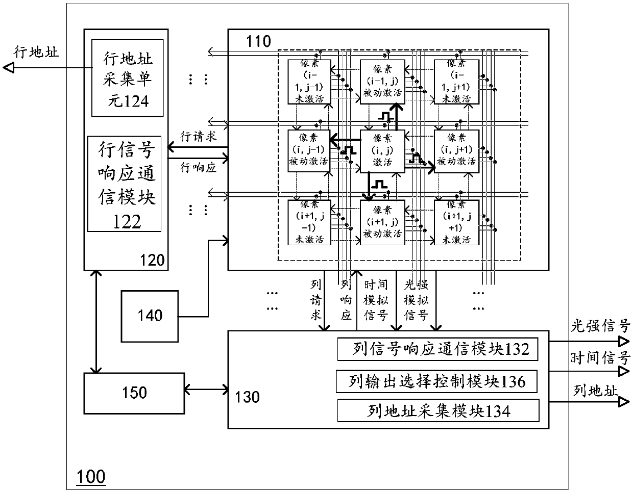
[0017] figure 1 A schematic diagram of an optical flow sensor 100 according to some embodiments of the invention is shown. The optical flow sensor 100 can be applied to high-speed moving object detection and tracking scenarios to extract optical flow algorithm parameters. According to an implementation manner, the optical flow sensor 100 is coupled with an external image acquisition system, and transmits the extracted optical flow...


PUM


Abstract

The invention discloses a pixel acquisition circuit which at least comprises a light intensity detector, a first state storage module, a second state storage module, a light intensity signal acquisition and storage module and a time information storage module. An optical flow sensor including the pixel acquisition circuit is also disclosed.

Description

technical field [0001] The invention relates to the technical field of image acquisition, in particular to a pixel acquisition circuit and an optical flow sensor. Background technique [0002] With the continuous development of information technology, computer vision and image information processing become more and more important. Among them, the optical flow method can determine the movement of the target object based on image information. It can be applied in many fields such as military aerospace, traffic supervision, information science, meteorology and medicine. [0003] The concept of optical flow was first proposed by Gibson in 1950. Objects can be imaged by photosensitive elements. The points in the image are in one-to-one correspondence with the points on the real object. When the target object moves in the three-dimensional scene, the image brightness pattern in the corresponding image frame sequence will show flow. This flow of image brightness patterns can b...

Claims


Application Information

Patent Timeline
Patent Type & Authority Applications(China)
IPC IPC(8): G01J1/16
CPCG01J1/16H04N25/772H04N25/771H04N25/75H04N25/745
Inventor 陈守顺
Owner OMNIVISION SENSOR SOLUTION (SHANGHAI) CO LTD
Why Eureka
Try Eureka